
Page 118 - Valve Selection Handbook
P. 118
Manual Valves 105
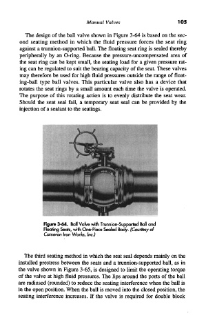
The design of the ball valve shown in Figure 3-64 is based on the sec-
ond seating method in which the fluid pressure forces the seat ring
against a trunnion-supported ball. The floating seat ring is sealed thereby
peripherally by an O-ring. Because the pressure-uncompensated area of
the seat ring can be kept small, the seating load for a given pressure rat-
ing can be regulated to suit the bearing capacity of the seat. These valves
may therefore be used for high fluid pressures outside the range of float-
ing-ball type ball valves. This particular valve also has a device that
rotates the seat rings by a small amount each time the valve is operated.
The purpose of this rotating action is to evenly distribute the seat wear.
Should the seat seal fail, a temporary seat seal can be provided by the
injection of a sealant to the seatings.
Figure 3-64. Ball Valve with Trunnion-Supported Ball and
Floating Seats, with One-Piece Sealed Body. (Courtesy of
Cameron Iron Works, Inc.)
The third seating method in which the seat seal depends mainly on the
installed prestress between the seats and a trunnion-supported ball, as in
the valve shown in Figure 3-65, is designed to limit the operating torque
of the valve at high fluid pressures. The lips around the ports of the ball
are radiused (rounded) to reduce the seating interference when the ball is
in the open position. When the ball is moved into the closed position, the
seating interference increases. If the valve is required for double block