
Page 141 - Valve Selection Handbook
P. 141
128 Valve Selection Handbook
lower than for fluids that have little lubricity or consist of solids, or when
the valve is operated infrequently. Manufacturers supply tables that give
the seating and unseating torques for various conditions of operation.
In the case of interference-seated butterfly valves above DN 400 (NFS
16) and conditions of high-flow velocities, the hydrodynamic and bear-
ing torques can greatly exceed the seating and unseating torques. The
operator for such valves may therefore have to be selected in consulta-
tion with the manufacturer.
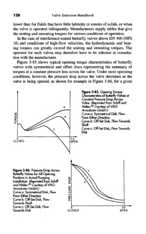
Figure 3-85 shows typical opening torque characteristics of butterfly
valves with symmetrical and offset discs representing the summary of
torques at a constant pressure loss across the valve. Under most operating
conditions, however, the pressure drop across the valve decreases as the
valve is being opened, as shown for example in Figure 3-86, for a given
Figure 3-85. Opening Torque
Characteristics of Butterfly Valves at
Constant Pressure Drop Across
Valve. (Reprinted from Schiffand
Hafen, 40 Courtesy of VAG-
Armaturen GmbH.)
Curve a: Symmetrical Disk, Flow
From Either Direction
Curve b: Off-Set Disk, Flow Towards
Shaft
Curve c: Off-Set Disk, Flow Towards
Disk
Figure 3-86. Pressure Drop Across
Butterfly Valves for All Opening
Positions in Actual Pumping
Installation. (Reprinted from Schiff
0
and Hafen/ Courtesy of VAG-
Armaturen GmbH.)
Curve a: Symmetrical Disk, Flow
From Either Direction
Curve b: Off-Set Disk, Flow
Towards Shaft
Curve c: Off-Set Disk, Flow
Towards Disk