
Page 136 - Valve Selection Handbook
P. 136
Manual Valves 123
The principle of the double offset location of the disc axis in combina-
tion with pressure-energized sealing in both directions applies also to the
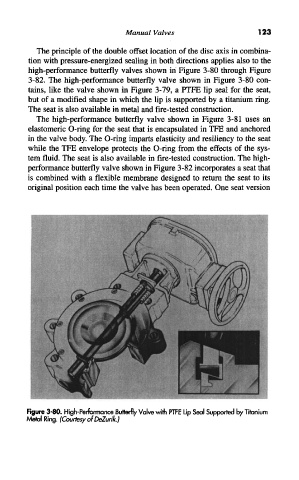
high-performance butterfly valves shown in Figure 3-80 through Figure
3-82. The high-performance butterfly valve shown in Figure 3-80 con-
tains, like the valve shown in Figure 3-79, a PTFE lip seal for the seat,
but of a modified shape in which the lip is supported by a titanium ring.
The seat is also available in metal and fire-tested construction.
The high-performance butterfly valve shown in Figure 3-81 uses an
elastomeric O-ring for the seat that is encapsulated in TFE and anchored
in the valve body. The O-ring imparts elasticity and resiliency to the seat
while the TFE envelope protects the O-ring from the effects of the sys-
tem fluid. The seat is also available in fire-tested construction. The high-
performance butterfly valve shown in Figure 3-82 incorporates a seat that
is combined with a flexible membrane designed to return the seat to its
original position each time the valve has been operated. One seat version
Figure 3-80. High-Performance Butterfly Valve with PTFE Lip Seal Supported by Titanium
Metal Ring. (Courtesy of DeZurik.)