
Page 131 - Valve Selection Handbook
P. 131
118 Valve Selection Handbook
Figure 3-73 illustrates the precautions that must be taken when
installing rubber-lined butterfly valves.
The flange of the rubber liner also serves as a sealing element against
the pipeline flanges. The installation of additional rubber gaskets
between pipe flanges and valve would tend to reduce the support of the
rubber liner and, consequently, reduce the sealing capacity of the valve.
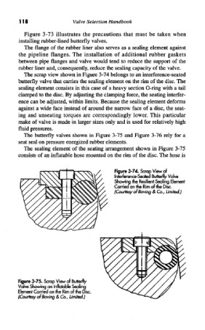
The scrap view shown in Figure 3-74 belongs to an interference-seated
butterfly valve that carries the sealing element on the rim of the disc. The
sealing element consists in this case of a heavy section O-ring with a tail
clamped to the disc. By adjusting the clamping force, the seating interfer-
ence can be adjusted, within limits. Because the sealing element deforms
against a wide face instead of around the narrow face of a disc, the seat-
ing and unseating torques are correspondingly lower. This particular
make of valve is made in larger sizes only and is used for relatively high
fluid pressures.
The butterfly valves shown in Figure 3-75 and Figure 3-76 rely for a
seat seal on pressure energized rubber elements.
The sealing element of the seating arrangement shown in Figure 3-75
consists of an inflatable hose mounted on the rim of the disc. The hose is
/, Figure 3-74. Scrap View of
Interference-Seated Butterfly Valve
Showing the Resilient Sealing Element
Carried on the Rim of the Disc.
(Courtesy of Boving & Co., Limited.)
Figure 3-75. Scrap View of Butterfly
Valve Showing an Inflatable Sealing
Element Carried on the Rim of the Disc.
(Courtesy of Boving & Co., Limited.)