
Page 132 - Valve Selection Handbook
P. 132
Manual Valves 119
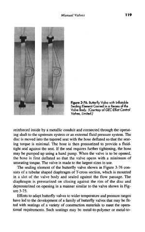
Figure 3-76. Butterfly Valve with Inflatable
Sealing Element Carried in a Recess of the
Valve Body. (Courtesy of GEC-Elliot Control
Valves, Limited.)
reinforced inside by a metallic conduit and connected through the operat-
ing shaft to the upstream system or an external fluid pressure system. The
disc is moved into the tapered seat with the hose deflated so that the seat-
ing torque is minimal. The hose is then pressurized to provide a fluid-
tight seal against the seat. If the seal requires further tightening, the hose
may be pumped up using a hand pump. When the valve is to be opened,
the hose is first deflated so that the valve opens with a minimum of
unseating torque. The valve is made to the largest sizes in use.
The sealing element of the butterfly valve shown in Figure 3-76 con-
sists of a tubular shaped diaphragm of T-cross section, which is mounted
in a slot of the valve body and sealed against the flow passage. The
diaphragm is pressurized on closing against the rim of the disc and
depressurized on opening in a manner similar to the valve shown in Fig-
ure 3-75.
Efforts to adapt butterfly valves to wider temperature and pressure ranges
have led to the development of a family of butterfly valves that may be fit-
ted with seatings of a variety of construction materials to meet the opera-
tional requirements. Such seatings may be metal-to-polymer or metal-to-