
Page 180 - Valve Selection Handbook
P. 180
Pressure Relief Valves 167
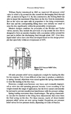
William Naylor introduced in 1863 an improved lift pressure relief
valve in which a lip around the disc turned the discharging fluid through
180°, as shown in Figure 5-2. By this construction, the flowing fluid was
able to impart the maximum lifting force on the disc from its momentum.
But as the valve can open only in proportion to the rising overpressure,
flow rate and the corresponding lifting force were initially too small to
raise the disc significantly within the permissible overpressure.
Modern designs combine the principles of the Ritchie and Taylor
valves; namely, they include the provision of a lip around the disc that is
designed to form an annular chamber with a secondary orifice around the
seat and to deflect the discharging fluid through about 180°. Over time,
liquid relief valves have also been developed based on this design princi-
ple that open fully within an overpressure of 10%.
Figure 5-2. Pressure Relief Valve,
Naylor Type.
All early pressure relief valves employed a weight for loading the disc
for two reasons. First, it was difficult at that time to produce a satisfacto-
ry spring. Second, objections were raised against the spring characteristic
to raise the loading as the disc rises.
However, a weight soon becomes very heavy and eventually impracti-
cal as valve size and operating pressure increase. Lever mounting of the
weight extends the range of application, but the lever cannot conveniently
be enclosed to prevent unauthorized interference with the pressure setting.
Spring loading overcomes these disadvantages. The spring characteris-
tic can also be matched to the lifting force characteristic that arises from
the fluid acting on the disc. For these reasons, nearly all direct-loaded
pressure relief valves are now spring loaded. Exceptions are pressure
relief valves for low-pressure duties, depending on Code of Practice.