
Page 182 - Valve Selection Handbook
P. 182
Pressure Relief Valves 169
The valve shown in Figure 5-4 offers a further protection to spring
overheating by mounting a lantern ring between valve body and bonnet.
The valve shown in Figure 5-6 is unique in that it incorporates an educ-
tor formed by channels around the disc. When the valve pops open, the
eductor becomes active and evacuates the chamber above the disc. The
purpose of the eductor is to assist sharp opening and closing of the valve.
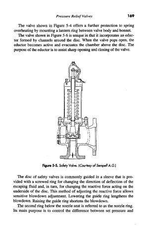
Figure 5-5. Safety Valve. (Courtesy of Sempell A.G.)
The disc of safety valves is commonly guided in a sleeve that is pro-
vided with a screwed ring for changing the direction of deflection of the
escaping fluid and, in turn, for changing the reactive force acting on the
underside of the disc. This method of adjusting the reactive force allows
sensitive blowdown adjustment. Lowering the guide ring lengthens the
blowdown. Raising the guide ring shortens the blowdown.
The second ring below the nozzle seat is referred to as the nozzle ring.
Its main purpose is to control the difference between set pressure and