
Page 225 - Valve Selection Handbook
P. 225
212 Valve Selection Handbook
unbalanced area of the main valve piston causes the main valve to open.
While the valve is open, a continuous small bleed into the dome above
the piston is maintained. When on receding overpressure the pilot closes,
the check valve returns to its closed position and closes the dome vent to
the atmosphere. The bleed entering the dome now closes the valve. The
perforated cone in the outlet connection of the main valve serves as a dif-
fuser type silencer.
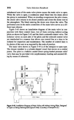
Figure 5-43 shows an installation diagram of the main valve in con-
junction with three control lines, two of them carrying indirect-acting
pilots as shown in Figure 5-42 and the third a solenoid control valve. The
isolation valves on each side of the pilots and the solenoid control valve
are interlocked in a manner that allows one control line at a time to be
isolated for inspection and maintenance. The number of control lines is
by choice of the user or as required by the code of practice.
The main valve shown in Figure 5-44 is of the energize-to-open type.
The closure member is a cylinder-shaped vessel that moves on a central
piston. The pilot is a bellows sealed direct spring-loaded pressure relief
valve that may be provided with supplementary loading and assisted lift-
ing by means of solenoids.
Figure 5-43. Installation Diagram of Main Valve with Indirect Acting Pilots, Designed
to Open on Being Deenergized (Typical Only). (Courtesy of Sempen A.G.)