
Page 57 - Video Coding for Mobile Communications Efficiency, Complexity, and Resilience
P. 57
34 Chapter 2. Video Coding: Fundamentals
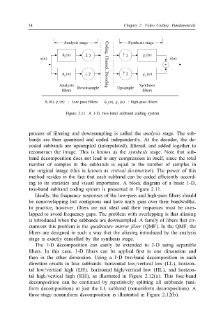
Analysis stage Synthesis stage
h 1 n) ( ↓ 2 ↑ 2 g 1 n) (
ˆ ) ( n
x (n ) x
+
h 2 n) ( ↓ 2 ↑ 2 g 2 n) (
Analysis Downsample Upsample Synthesis
Coding, Channel, Decoding
filters filters
h ), ( n g 1 ) ( n : low-pass filters ( n ), g 2 ) ( n : high-pass filters
1 h 2
Figure 2.11: A 1-D, two-band subband coding system
process of ltering and downsampling is called the analysis stage. The sub-
bands are then quantized and coded independently. At the decoder, the de-
coded subbands are upsampled (interpolated), ltered, and added together to
reconstruct the image. This is knows as the synthesis stage. Note that sub-
band decomposition does not lead to any compression in itself, since the total
number of samples in the subbands is equal to the number of samples in
the original image (this is known as critical decimation). The power of this
method resides in the fact that each subband can be coded eGciently accord-
ing to its statistics and visual importance. A block diagram of a basic 1-D,
two-band subband coding system is presented in Figure 2.11.
Ideally, the frequency responses of the low-pass and high-pass lters should
be nonoverlapping but contiguous and have unity gain over their bandwidths.
In practice, however, lters are not ideal and their responses must be over-
lapped to avoid frequency gaps. The problem with overlapping is that aliasing
is introduced when the subbands are downsampled. A family of lters that cir-
cumvent this problem is the quadrature mirror lter (QMF). In the QMF, the
lters are designed in such a way that the aliasing introduced by the analysis
stage is exactly cancelled by the synthesis stage.
The 1-D decomposition can easily be extended to 2-D using separable
lters. In this case, 1-D lters can be applied rst in one dimension and
then in the other dimension. Using a 1-D two-band decomposition in each
direction results in four subbands: horizontal low=vertical low (LL), horizon-
tal low=vertical high (LH), horizontal high=vertical low (HL), and horizon-
tal high=vertical high (HH), as illustrated in Figure 2.12(a). This four-band
decomposition can be continued by repetitively splitting all subbands (uni-
form decomposition) or just the LL subband (nonuniform decomposition). A
three-stage nonuniform decomposition is illustrated in Figure 2.12(b).