
Page 332 - Materials Chemistry, Second Edition
P. 332
CAT3525_C10.qxd 1/31/2005 12:00 PM Page 303
The Sanitary Landfill 303
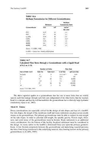
TABLE 10.6
Methane Transmission for Different Geomembranes
Methane
Thickness Transmission Rate
Geomembrane mm mil (ml/m 2
day atm)
PVC 0.25 10 4.4
PVC 0.5 20 3.3
LLDPE 0.45 18 2.3
CSPE 0.8 32 0.27
CSPE 0.85 34 1.6
HDPE 0.6 24 1.3
HDPE 0.85 34 1.4
Source: U.S EPA, 1988.
LLDPE Linear low- density polyethylene
TABLE 10.7
Calculated Flow Rates through a Geomembrane with a Liquid Head
of 0.3 m (1 ft)
Number of Holes Flow Rate
2
Size of Hole (cm ) hole/ha hole/acre L/m /day gal/acre/day
2
No holes 0 0 9.4 10 6 0.01
0.1 2.5 1 0.31 330
0.1 75 30 9.4 10,000
1 2.5 1 3.1 3,300
1 75 30 94 100,000
10 2.5 1 31 33,000
Source: U.S. EPA, 1991.
The above equation applies to a geomembrane that has one or more holes that are widely
spaced, such that leakage through each hole acts independent of the other holes, that the leachate
head h is constant, and that the soil that underlies the geomembrane has a relatively large hydraulic
conductivity (Qian et al., 2002).
10.4.11 STRESS
Stress considerations are especially critical for the design of side slopes and base of a landfill.
For side slopes, the weight of the membrane itself and waste settlement can place severe tensile
strains on the geomembrane. The primary geomembrane must be able to support its own weight
on the side slopes. In order to calculate self-weight, the specific gravity, friction angle, thick-
ness, and yield stress of the geomembrane must be known. Waste settlement is an additional
stress consideration. For the bottom of the facility, localized settlement must be considered in
the design. As waste settles in the landfill a downward force acts upon the primary geomem-
brane. A low friction component between the geomembrane and underlying material prevents
the force from being transferred to the underlying material, thus limiting tension on the primary
geomembrane (U.S. EPA, 1989).