
Page 150 - Wastewater Solids Incineration Systems
P. 150
Heat Recovery and Reuse 117
of auxiliary fuel, heat recovery through recuperation was attempted. Fuel savings
were 35 to 75% at 540°C (1000°F) air preheat and combustion could be self-sustaining
at 650°C (1200°F) and a well-dewatered feed cake (25 to 27% solids). Recuperation is
the most basic and cost-effective form of heat recovery.
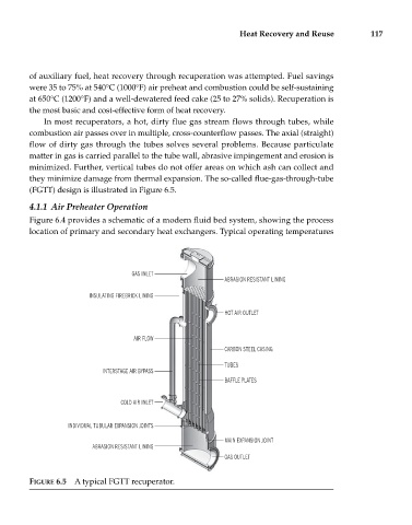
In most recuperators, a hot, dirty flue gas stream flows through tubes, while
combustion air passes over in multiple, cross-counterflow passes. The axial (straight)
flow of dirty gas through the tubes solves several problems. Because particulate
matter in gas is carried parallel to the tube wall, abrasive impingement and erosion is
minimized. Further, vertical tubes do not offer areas on which ash can collect and
they minimize damage from thermal expansion. The so-called flue-gas-through-tube
(FGTT) design is illustrated in Figure 6.5.
4.1.1 Air Preheater Operation
Figure 6.4 provides a schematic of a modern fluid bed system, showing the process
location of primary and secondary heat exchangers. Typical operating temperatures
GAS INLET
ABRASION RESISTANT LINING
INSULATING FIREBRICK LINING
HOT AIR OUTLET
AIR FLOW
CARBON STEEL CASING
TUBES
INTERSTAGE AIR BYPASS
BAFFLE PLATES
COLD AIR INLET
INDIVIDUAL TUBULAR EXPANSION JOINTS
MAIN EXPANSION JOINT
ABRASION RESISTANT LINING
GAS OUTLET
FIGURE 6.5 A typical FGTT recuperator.