
Page 273 - Wastewater Solids Incineration Systems
P. 273
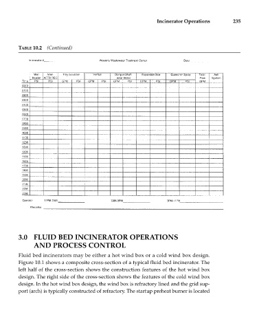
Incinerator Operations        235


             TABLE 10.2  (Continued)


             3.0 FLUID BED INCINERATOR OPERATIONS
                   AND PROCESS CONTROL

             Fluid bed incinerators may be either a hot wind box or a cold wind box design.
             Figure 10.1 shows a composite cross-section of a typical fluid bed incinerator. The
             left half of the cross-section shows the construction features of the hot wind box
             design. The right side of the cross-section shows the features of the cold wind box
             design. In the hot wind box design, the wind box is refractory lined and the grid sup-
             port (arch) is typically constructed of refractory. The startup preheat burner is located