
Page 340 - Wastewater Solids Incineration Systems
P. 340
Appendix B Incineration Subsystems 301
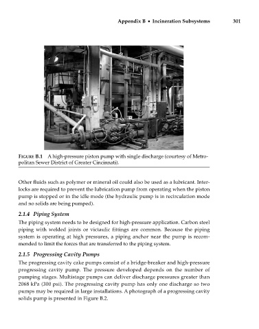
FIGURE B.1 A high-pressure piston pump with single discharge (courtesy of Metro-
politan Sewer District of Greater Cincinnati).
Other fluids such as polymer or mineral oil could also be used as a lubricant. Inter-
locks are required to prevent the lubrication pump from operating when the piston
pump is stopped or in the idle mode (the hydraulic pump is in recirculation mode
and no solids are being pumped).
2.1.4 Piping System
The piping system needs to be designed for high-pressure application. Carbon steel
piping with welded joints or victaulic fittings are common. Because the piping
system is operating at high pressures, a piping anchor near the pump is recom-
mended to limit the forces that are transferred to the piping system.
2.1.5 Progressing Cavity Pumps
The progressing cavity cake pumps consist of a bridge-breaker and high-pressure
progressing cavity pump. The pressure developed depends on the number of
pumping stages. Multistage pumps can deliver discharge pressures greater than
2068 kPa (300 psi). The progressing cavity pump has only one discharge so two
pumps may be required in large installations. A photograph of a progressing cavity
solids pump is presented in Figure B.2.