
Page 96 - Wastewater Solids Incineration Systems
P. 96
Combustion Technology 65
Sand Silo Flue Gas Expansion
Tank Chemical
Silo
Stack
Incinerator Fin Fan
Cooler
Heat
Exchanger Building Usage
Economizer
Sludge
ID Fan
Bag
Filter
Hot
Air for Water
Fluidization Circuit
Natural Gas Ash Silo
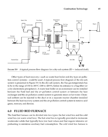
FIGURE 5.9 A typical process flow diagram for a dry-ash system (ID induced draft).
Other types of heat recovery—such as waste heat boiler and dry type air pollu-
tion control systems—could be used. A typical process flow diagram of the dry-ash
system is presented in Figure 5.9. In the dry-ash system, the flue gas temperature has
to be in the range of 150 to 205°C (300 to 400°F), before its entrance to a bag-filter (or
a dry electrostatic precipitator). A waste heat boiler or an economizer can be installed
between the fluid bed and the air pollution control system or between the heat
exchanger and the air pollution control system to generate steam or hot water. Chem-
ical sorbent can be injected to the duct or in a separate reactor chamber installed
between the heat recovery system and the air pollution control system to remove acid
gases, mercury, and dioxins.
6.0 FLUID BED FURNACE
The fluid bed furnace can be divided into two types: the hot wind box and the cold
wind box (or warm wind box). The hot wind box is typically provided to incinerate
wastewater solids that typically have low heat values and that require intensive air
preheating to minimize auxiliary fuel consumption. The cold wind box furnace is