Page 143 - Water Engineering Hydraulics, Distribution and Treatment
P. 143

121
                                                                                                                  5.2 Fluid Transport
                                                                                          6. The Nanzenji aqueduct water channel of Kyoto,
                                                                                            Japan (Fig. 5.9).
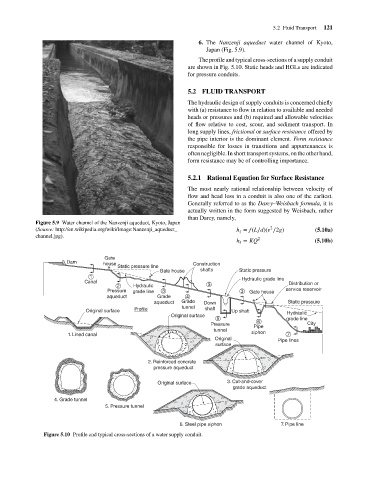
                                                                                          The profile and typical cross-sections of a supply conduit
                                                                                      are shown in Fig. 5.10. Static heads and HGLs are indicated
                                                                                      for pressure conduits.
                                                                                      5.2 FLUID TRANSPORT
                                                                                      The hydraulic design of supply conduits is concerned chiefly
                                                                                      with (a) resistance to flow in relation to available and needed
                                                                                      heads or pressures and (b) required and allowable velocities
                                                                                      of flow relative to cost, scour, and sediment transport. In
                                                                                      long supply lines, frictional or surface resistance offered by
                                                                                      the pipe interior is the dominant element. Form resistance
                                                                                      responsible for losses in transitions and appurtenances is
                                                                                      often negligible. In short transport systems, on the other hand,
                                                                                      form resistance may be of controlling importance.
                                                                                      5.2.1 Rational Equation for Surface Resistance
                                                                                      The most nearly rational relationship between velocity of
                                                                                      flow and head loss in a conduit is also one of the earliest.
                                                                                      Generally referred to as the Darcy–Weisbach formula,itis
                                                                                      actually written in the form suggested by Weisbach, rather
                                                                                      than Darcy, namely,
                                    Figure 5.9 Water channel of the Nanzenji aqueduct, Kyoto, Japan
                                                                                                                 2
                                    (Source: http://en.wikipedia.org/wiki/Image:Nanzenji_aqueduct_    h = f(L∕d)(v ∕2g)         (5.10a)
                                                                                                       f
                                    channel.jpg).                                                            2
                                                                                                      h = KQ                    (5.10b)
                                                                                                       f
                                                           Gate
                                              Dam         house                         Construction
                                                               Static pressure line
                                                                             Gate house   shafts       Static pressure
                                                      1                                                 Hydraulic grade line
                                                    Canal                                                              Distribution or
                                                               2    Hydraulic                3
                                                            Pressure  grade line  3                     3  Gate house  service reservoir
                                                           aqueduct         Grade     4
                                                                           aqueduct  Grade  Down                       Static pressure
                                                    Original surface  Profile       tunnel  shaft    Up shaft          Hydraulic
                                                                                 Original surface
                                                                                                5                      grade line
                                                                                                             6
                                                                                              Pressure      Pipe              City
                                                                                               tunnel      siphon
                                              1. Lined canal                                                           7
                                                                                               Original             Pipe lines
                                                                                               surface
                                                                         2. Reinforced concrete
                                                                            pressure aqueduct

                                                                            Original surface       3. Cut-and-cover
                                                                                                         grade aqueduct
                                          4. Grade tunnel
                                                           5. Pressure tunnel


                                                                                   6. Steel pipe siphon              7. Pipe line
                                       Figure 5.10 Profile and typical cross-sections of a water supply conduit.
   138   139   140   141   142   143   144   145   146   147   148