
Page 144 - Water Engineering Hydraulics, Distribution and Treatment
P. 144
122
Chapter 5
Water Hydraulics, Transmission, and Appurtenances
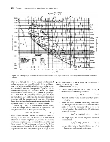
Figure 5.11 Moody diagram with the friction factor f, as a function of Reynolds number R, in Darcy–Weisbach formula for flow in
conduits.
where h is the head loss in ft (m) (energy loss because of √
f R∕ f with scales for f and R added for convenience in
surface resistance) in a pipe of length L in ft (m) and diame- finding f for use in Eq. (5.10a).
ter d in ft (m) through which a fluid is transported at a mean In reference to R and ∕r,:
3
3
velocity v in ft/s (m/s) and flow rate Q in ft /s (m /s); g is the 1. Laminar flow persists until R = 2,000, and the f:R
2
2
acceleration of gravity, 32.2 ft/s (9.81 m/s ); f is a dimen-
2 5 relationship is quite simply as follows:
sionless friction factor (see Fig. 5.11); and K = 8fL∕ gd .
In the more than 100 years of its existence, use, and study, f = 64∕R (5.12a)
this formulation has been foremost in the minds of engineers
Reynolds number R and friction factor f are dimen-
concerned with the transmission of water as well as other
sionless.
fluids. That this has often been so in a conceptual rather than
2. Above R = 4,000, turbulent flow is fully established,
a practical sense does not detract from its importance.
and the single trace for laminar flow branches into a
Within Eq. (5.10a), the dimensionless friction factor f
family of curves for increasing values of ∕r above
is both its strength and its weakness in applications—its
a lower boundary that identifies the f:R relationship
strength as a function of the Reynolds number R,
for smooth pipes as
R = vd ∕ = vd∕ (5.11)
√ √
1∕ f = 2 log R f − 0.8 (5.13)
where is the absolute viscosity, = ∕ is the kinematic
viscosity of the fluid, and is its density; its weakness as 3. For rough pipes, the relative roughness ∕r takes
a function of relative roughness ∕r, where is a measure command and
of absolute roughness and r is the inside radius of the pipe √
1∕ f = 2 log r∕ + 1.74 (5.14)
(2 ∕d = ∕r). The f:R relationship is shown in Fig. 5.11, a
general resistance diagram for flow in uniform conduits. This where r is the radius of the pipe (ft or m) and ∕r is
√
diagram evolves from a logarithmic plot of 1∕ f against the relative roughness, dimensionless.