Page 184 - Water Engineering Hydraulics, Distribution and Treatment
P. 184

162
                                          Chapter 5
                                                   Water Hydraulics, Transmission, and Appurtenances
                                                                                       (a) air displaced while the line is being filled and (b) air
                                                          L c
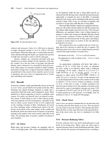
                                                             Air inlet and outlet
                                                                                       released from the flowing water when the pressure decreases
                                                                                       appreciably or summits lie close to the HGL. A manually
                                                                                       operated cock or gate can be substituted if the pressure at the
                                                             Float
                                                                                       summit is high. Little, if any, air will then accumulate, and
                                                             valve
                                                                                       air needs to escape only while the line is being filled.
                                                   Water line
                                                                                          Steel and other flexible conduits are equipped with auto-
                                                                                       matic air valves that will also admit air to the line and prevent
                                                                                       its collapse under negative pressure (see Fig. 5.26). Pressure
                                                                                       differences are generated when a line is being drained on
                                                                                       purpose or when water escapes accidentally through a break
                                                                                       at a low point. Locations of choice are both sides of gates
                                              Attach to pipe                           at summits, the downstream side of other gates, and changes
                                                                                       in grade to steeper slopes in sections of line not otherwise
                                    Figure 5.26 Air inlet and release valve.
                                                                                       protected by air valves.
                                                                                          The required valve size is related to the size of the con-
                                                                                       duit, and to the velocities at which the line is emptied. The
                                    reducers and increasers. Gates 8 in. (200 mm) in diameter
                                                                                       following ratios of air valve size to conduit diameter provide
                                    or larger commonly include a 4 or 6 in. (100 or 150 mm)
                                                                                       common but rough estimates of needed sizes:
                                    gated bypass. When the larger gate is seated under pressure,
                                    water admitted through the bypass can equalize the pressure
                                                                                         For release of air only:  1:12 or 1 in./ft (83 mm/m)
                                    on both sides and make it easier to lift the main gate.
                                                                                         For admission as well as release of air:  1:8 or 1.5 in./ft
                                        Gravity conduits are commonly provided with gate
                                                                                           (125 mm/m).
                                    chambers (a) at points strategic for the operation of the sup-
                                    ply conduit, (b) at the two ends of sag pipes and pressure
                                                                                          An approximate calculation will show that under a
                                    tunnels, and (c) wherever it is convenient to drain given sec-
                                                                                       vacuum of 48 in. (1,220 mm) of water, an automatic
                                    tions. Sluice gates are normally installed in grade conduits,
                                                                                       air valve, acting as an injection orifice with a coefficient
                                    particularly in large ones. In special situations, needle valves                      (       −3  )
                                                                                       of discharge of 0.5 under a head of 4∕ 1.3 × 10  =
                                    are preferred for fine control of flow, butterfly valves for ease
                                                                                       3,080 ft (939 m) of air of specific gravity 1.3 × 10, is
                                    of operation, and cone valves for regulating time of closure               √                 3
                                                                                       expected to admit about 0.5 2g × 3,080 = 220 ft ∕sof
                                    and controlling water hammer.                         2  (    3         2  )
                                                                                       air/ft  67.2m ∕sof air∕m  of valve. If the diameter ratio
                                                                                       is 1:8, the displacement velocity in the conduit can be as high
                                    5.9.2 Blowoffs                                     as 220∕64 = 3.5ft∕s(1 m∕s) without exceeding a vacuum
                                                                                       of 48 in. (1,220 mm) of water. A similar calculation will
                                    In pressure conduits, small, gated takeoffs, known as blowoff  show the rate of release of air. The amounts of air that can be
                                    or scour valves, are provided at low points in the line. They  dissolved by water at atmospheric pressure are about 2.9%
                                    discharge into natural drainage channels or empty into a  by volume at 32 F(0 C) and 1.9% at 77 F(25 C), changing
                                                                                                       ◦
                                                                                                   ◦
                                                                                                                      ◦
                                                                                                                           ◦
                                    sump from which the water can be pumped to waste. There  in direct proportion to the pressure. Accordingly, they are
                                    should be no direct connection to sewers or polluted water  doubled at 2 atm or 14.7 psig (102 kPa gauge).
                                    courses. For safety, two blowoff valves are placed in series.
                                    The chance of both failing to close is thus reduced greatly.
                                    Their size depends on local circumstances, especially on the  5.9.4 Check Valves
                                    time in which a given section of line is to be emptied and  Check valves are used to maintain flow in one direction only
                                    on the resulting velocities of flow. Calculations are based  by closing when the flow begins to reverse. They are placed
                                    on orifice discharge under a falling head, equal to the dif-  on force mains to prevent backflow when pumps shut down.
                                    ference in elevation of the water surface in the conduit and  When the flow is in the same direction as the specified direc-
                                    the blowoff, minus the friction head. Frequency of operation  tion of the check valve, the valve is considered to be fully
                                    depends on the quality of the water carried, especially on silt  open.
                                    loads. The drainage gates of gravity conduits are placed in
                                    gate chambers.
                                                                                       5.9.5 Pressure-Reducing Valves
                                                                                       Pressure-reducing valves are used to keep pressures at safe
                                    5.9.3 Air Valves
                                                                                       levels in low-lying areas. These valves are often used to
                                    Rigid pipes and pressure conduits are equipped with air  separate pressure zones in water distribution networks. These
                                    valves at all high points. The valves automatically remove  valves prevent the pressure downstream from exceeding a
   179   180   181   182   183   184   185   186   187   188   189