
Page 183 - Water Engineering Hydraulics, Distribution and Treatment
P. 183
Blowoff
5"
16
Hydraulic gradient
Distributing reservoir
Static head
1"
4
M O N 5.9 Appurtenances 161
L
Sugar tank Gate Blowoff 1" 4
Air valve K
Gate
5" 16
J
Air valve 3" 8 I
7" 16 H Length of pipe or stationing of line
Static head Hydraulic gradient Blowoff 7" 3" 16 8 1" 2 G F
Air valve 5" 16 E D
Gate 1" 4
Air valve Thickness of pipe C
Blowoff 5" 16
Intake reservoir Gate 1" 4 B
A
1" 4 5" 16 3" 8 7" 16 1" 2
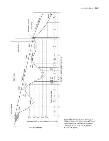
Figure 5.25 Profile of pipeline showing pipe
thickness and location of gates, blowoffs, and air
Allowable head for given thickness
valves (not to scale, vertical scale magnified).
′′
Conversion factors: 1 = 1in. = 25.4 mm;
′
1 = 1ft = 0.3048 m.
Elevation (ft)