Page 178 - Water Engineering Hydraulics, Distribution and Treatment
P. 178

156
                                                   Water Hydraulics, Transmission, and Appurtenances
                                          Chapter 5
                                      EXAMPLE 5.51 PRESSURE INTENSITY AND FORCE OF PIPE’S MECHANICAL JOINTS
                                      In jointed cast iron pipes, the longitudinal stresses can be resisted by the mechanical joints. Determine the pressure intensity and total
                                      force resisted by the mechanical joints of a 24 in. (609.6 mm) bell-and-spigot cast iron pipe.
                                      Solution 1 (US Customary System):
                                                                        p = [3,800∕(d + 6)] − 40
                                                                         = [3,800∕(24 + 6)] − 40
                                                                         = 86.66 psig.
                                                                                           2
                                                                       P = [3,000∕(d + 6) − 31]d
                                                                        f
                                                                         = [3,000∕(24 + 6) − 31](24) 2
                                                                         = 39,744 lb.
                                      Solution 2 (SI System):
                                                                        p = [670,000∕(d + 152)] − 278
                                                                         = [670,000∕(609.6 + 152)] − 278
                                                                         = 601.73 kPa gauge.
                                                                       P = [525∕(d + 152) − 0.2]d 2
                                                                        f
                                                                         = [525∕(609.6 + 152) − 0.2](609.6) 2
                                                                         = 181,844 N.
                                        Tables of standard dimensions and laying lengths are
                                    found in professional manuals, specifications of the Ameri-
                                    can Water Works Association (AWWA), and publications of
                                    manufacturers and trade associations.
                                    5.7 LOCATION
                                    Supply conduits are located in much the same way as rail-
                                    roads and highways.


                                    5.7.1 Line and Grade
                                    The invert of a grade aqueduct or grade tunnel is placed on the
                                    same slope as the HGL. Cut and fill, as well as cut and cover,
                                    are balanced to maintain a uniform gradient and reduce haul.
                                    Valleys and rivers that would be bridged by railroads and
                                    highways may be bridged also by aqueducts. Such indeed
                                    was the practice of ancient Rome, but modern aqueducts no
                                    longer rise above valley, stream, and hamlet except where a
                                    bridge is needed primarily to carry road or railway traffic.
                                    Pressure conduits have taken their place. Sometimes they
                                    are laid in trenches as sag pipes to traverse valleys and pass
                                    beneath streams; sometimes they strike deep below Earth’s
                                    surface in pressure tunnels for which geologic exploration
                                    fixes both line and grade.
                                        Pressure aqueducts and pipelines move freely up and
                                    down slopes. For economy they should hug the HGL in pro-
                                    file and a straight line in plan (Fig. 5.23). The size and thick-
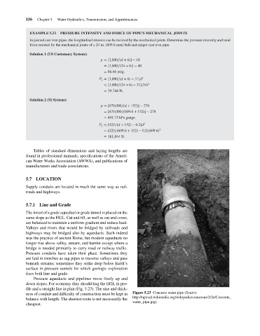
                                    ness of conduit and difficulty of construction must be kept in  Figure 5.23 Concrete water pipe (Source:
                                                                                       http://upload.wikimedia.org/wikipedia/commons/2/2e/Concrete_
                                    balance with length. The shortest route is not necessarily the
                                                                                       water_pipe.jpg).
                                    cheapest.
   173   174   175   176   177   178   179   180   181   182   183