
Page 173 - Water Engineering Hydraulics, Distribution and Treatment
P. 173
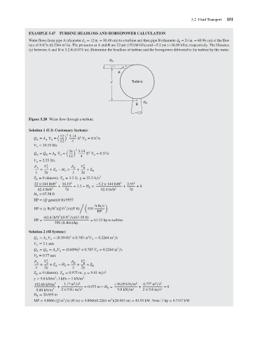
EXAMPLE 5.47 TURBINE HEADLOSS AND HORSEPOWER CALCULATION
Water flows from pipe A (diameter d = 12 in. = 30.48 cm) to a turbine and then pipe B (diameter d = 24 in. = 60.96 cm) at the flow
A
3
3
rate of 8 ft /s (0.2264 m /s). The pressures at A and B are 22 psi (152.68 kPa) and −5.2 psi (−36.09 kPa), respectively. The Distance
(y) between A and B is 3.2 ft (0.975 m). Determine the headloss of turbine and the horsepower delivered to the turbine by the water.
d
A
A
y
Turbine
d B 5.2 Fluid Transport 151
B B
Figure 5.20 Water flow through a turbine.
Solution 1 (U.S. Customary System):
( 12 ) 2 3.14
2
3
Q = A V = ft V = 8ft /s
A A A A
12 4
V = 10.19 ft/s
A
) 2
24 3.14
(
3
2
Q = Q = A V = ft V = 8ft /s
A
B
B
B
B
12 4
V = 2.55 ft/s
B
P A V A 2 P B V 2 B
+ + Z − H = + + Z
2g A T 2g B
Z = 0 (datum); Z = 3.2ft; g = 32.2ft∕s 2
A
B
22 × 144 lb/ft 2 10.19 2 −5.2 × 144 lb/ft 2 2.55 2
+ + 3.2 − H = + + 0
T
62.4lb/ft 3 2g 62.4lb/ft 3 2g
H = 67.58 ft
T
HP = (Q gpm)(H ft)/3957
/( )
ft-lb∕s
3
3
HP = ( lb∕ft )(Q ft ∕s)(H ft) 550
HP
3
3
(62.4lb/ft )(8 ft ∕s)(67.58 ft)
HP = = 61.33 hp to turbine
550 (ft-lb/s)/hp
Solution 2 (SI System):
2
3
2
Q = A V = (0.3048) × 0.785 m V = 0.2264 m ∕s
A
A A
A
V = 3.1m/s
A
2
3
Q = Q = A V = (0.6096) × 0.785 V = 0.2264 m ∕s
B
B
B B
A
V = 0.77 m/s
B
P A V A 2 P B V 2 B
+ + Z − H = + + Z
2g A T 2g B
Z = 0 (datum); Z = 0.975 m; g = 9.81 m∕s 2
B
A
3
= 9.8kN/m ;1 kPa = 1kN/m 2
2
2
2
2
152.68 kN/m 2 3.1 m ∕s 2 −36.09 kN∕m 2 0.77 m ∕s 2
+ + 0.975 m − H = + + 0
T
9.80 kN/m 3 2 × 9.81 m∕s 2 9.8kN∕m 3 2 × 9.8m∕s 2
H = 20.695 m
T
3
3
MP = 9.8066 (Q m ∕s) (H m) = 9.8066(0.2264 m )(20.695 m) = 45.95 kW. Note: 1 hp = 0.7457 kW