Page 174 - Water Engineering Hydraulics, Distribution and Treatment
P. 174

152
                                          Chapter 5
                                                   Water Hydraulics, Transmission, and Appurtenances
                                    5.2.4 Hydraulic Transients
                                                                                              11
                                    Transmission lines are subjected to transient pressures when
                                                                                                      2. Pressure tunnel
                                                                                              10
                                                                                                      3. River crossing
                                    valves are opened or closed or when pumps are started or
                                    stopped. Water hammer and surge are among such transient
                                    phenomena.
                                        Water hammer is the pressure rise accompanying a sud-
                                    den change in velocity. When velocity is decreased in this
                                    way, energy of motion must be stored by elastic deformation
                                    of the system. The sequence of phenomena that follows sud-
                                    den closure of a gate, for example, is quite like what would
                                    ensue if a long, rigid spring, traveling at uniform speed, were
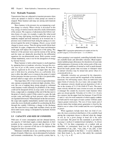
                                    suddenly stopped and held stationary at its forward end. A  Cost (10 4  dollars) (c)  12 9 8 7 6 5 4 3 2  1. Low-pressure pipe  Tunnel
                                    pressure wave would travel back along the spring as it com-  1
                                    pressed against the point of stoppage. Kinetic energy would
                                    change to elastic energy. Then the spring would vibrate back  0  10   20    30   40    50   60
                                    and forth. In a pipe, compression of the water and distention          Head loss (ft) (h)
                                    of the pipe wall replace the compression of the spring. The
                                                                                       Figure 5.21 Lagrangian optimization of conduit sections by
                                    behavior of the pressure wave and the motion of the spring  parallel tangents. Conversion factor: 1 ft = 0.3048 m.
                                    and the water are identically described by the differential
                                    equations for one-dimensional waves. Both systems would
                                                                                       where pumping is not required, controlling hydraulic factors
                                    vibrate indefinitely, were it not for the dissipation of energy
                                                                                       are available heads and allowable velocities. Head require-
                                    by internal friction.
                                                                                       ments include proper allowances for drawdown of reservoirs
                                        Water hammer is held within bounds in small pipelines
                                                                                       and maintenance of pressure in the various parts of the com-
                                    by operating them at moderate velocities, because the pres-
                                                                                       munity, under conditions of normal as well as peak demand.
                                    sure rise in psi or kPa cannot exceed about 50 times the
                                                                                       Reservoir heads greater than necessary to transport water
                                    velocity expressed in ft/s or m/s. In larger lines the pres-
                                                                                       at normal velocities may be turned into power when it is
                                    sure is held down by arresting flows at a sufficiently slow
                                                                                       economical to do so.
                                    rate to allow the relief wave to return to the point of control
                                                                                          Allowable velocities are governed by the characteris-
                                    before pressures become excessive. If this is not practicable,
                                                                                       tics of the water carried and the magnitude of the hydraulic
                                    pressure relief or surge valves are introduced.
                                                                                       transients. For silt-bearing waters, there are both lower and
                                        Very large lines, 6 ft (1.8 m) or more in equivalent diam-
                                                                                       upper limits of velocity; for clear water, only an upper limit.
                                    eter, operate economically at relatively high velocities. How-
                                                                                       The minimum velocity should prevent deposition of silt; it
                                    ever, the cost of making them strong enough to withstand
                                                                                       lies in the vicinity of 2–2.5 ft/s (0.60–0.75 m/s). The maxi-
                                    water hammer would ordinarily be prohibitive if the energy
                                                                                       mum velocity should not cause erosion or scour, nor should
                                    could not be dissipated slowly in surge tanks. In its simplest
                                                                                       it endanger the conduit by excessive water hammer when
                                    form, a surge tank is a standpipe at the end of the line next to
                                                                                       gates are closed quickly. Velocities of 4–6 ft/s (1.2–1.8 m/s)
                                    the point of velocity control. If this control is a gate, the tank
                                                                                       are common, but the upper limit lies between 10 and 20 ft/s
                                    accepts water and builds up back pressure when velocities
                                                                                       (3 and 6.1 m/s) for most materials of which supply conduits
                                    are regulated downward. When demand on the line increases,
                                                                                       are built and for most types of water carried. Unlined canals
                                    the surge tank supplies immediately needed water and gen-
                                                                                       impose greater restrictions. The size of force mains and of
                                    erates the excess hydraulic gradient for accelerating the flow
                                                                                       gravity mains that include power generation is fixed by the
                                    through the conduit. Following a change in the discharge
                                                                                       relative cost or value of the conduit and the cost of pumping
                                    rate, the water level in a surge tank oscillates slowly up and
                                                                                       or power.
                                    down until excess energy is dissipated by hydraulic friction
                                                                                          When aqueducts include more than one kind of con-
                                    in the system.
                                                                                       duit, the most economical distribution of the available head
                                                                                       among the component classes is effected when the change
                                    5.3 CAPACITY AND SIZE OF CONDUITS
                                                                                       in cost Δc for a given change in head Δh is the same
                                    With rates of water consumption and fire demand known,  for each kind. The proof for this statement is provided by
                                    the capacity of individual supply conduits depends on their  Lagrange’s method of undetermined multipliers. As shown
                                    position in the waterworks system and the choice of the  in Fig. 5.21 for three components of a conduit with an
                                    designer for (a) a structure of full size or (b) duplicate lines  allowable, or constrained, head loss H, the Lagrangian
                                    staggered in time of construction.                 requirement of Δc ∕Δh =Δc ∕Δh =Δc ∕Δh is met
                                                                                                                2
                                                                                                      1
                                                                                                          1
                                                                                                                           3
                                                                                                                     2
                                                                                                                               3
                                        Minimum workable size is one controlling factor in the  when parallel tangents to the three c : h curves identify, by
                                    design of tunnels. Otherwise, size is determined by hydraulic  trial, three heads h , h , and h that satisfy the constraint
                                                                                                                3
                                                                                                      1
                                                                                                         2
                                    and economic considerations. For a gravity system, that is,  h + h + h = H.
                                                                                        1
                                                                                                 3
                                                                                            2
   169   170   171   172   173   174   175   176   177   178   179