
Page 177 - Water Engineering Hydraulics, Distribution and Treatment
P. 177
155
5.6 Structural Requirements
arch at half depth, two lateral arcs struck by radii equaling
the height of the crown above the invert, and a circular arc of
like radius establishing the bottom.
5.6 STRUCTURAL REQUIREMENTS
Structurally, closed conduits must resist a number of different
forces singly or in combination:
1. Internal pressure equal to the full head of water to
which the conduit can be subjected
2. Unbalanced pressures at bends, contractions, and clo-
sures
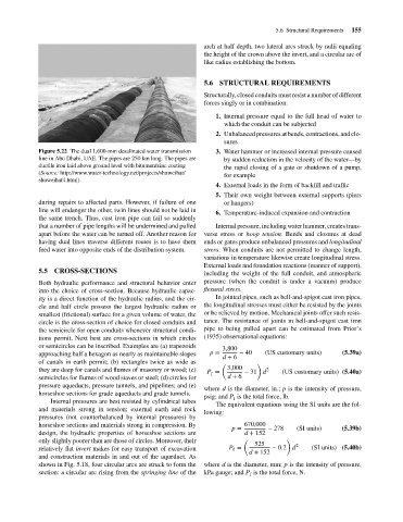
Figure 5.22 The dual 1,600-mm desalinated water transmission 3. Water hammer or increased internal pressure caused
line in Abu Dhabi, UAE. The pipes are 250 km long. The pipes are by sudden reduction in the velocity of the water—by
ductile iron laid above ground level with bitumen/zinc coating the rapid closing of a gate or shutdown of a pump,
(Source: http://www.water-technology.net/projects/shuweihat/
for example
shuweihat4.html).
4. External loads in the form of backfill and traffic
5. Their own weight between external supports (piers
during repairs to affected parts. However, if failure of one or hangers)
line will endanger the other, twin lines should not be laid in
6. Temperature-induced expansion and contraction
the same trench. Thus, cast iron pipe can fail so suddenly
that a number of pipe lengths will be undermined and pulled Internal pressure, including water hammer, creates trans-
apart before the water can be turned off. Another reason for verse stress or hoop tension. Bends and closures at dead
having dual lines traverse different routes is to have them ends or gates produce unbalanced pressures and longitudinal
feed water into opposite ends of the distribution system. stress. When conduits are not permitted to change length,
variations in temperature likewise create longitudinal stress.
External loads and foundation reactions (manner of support),
5.5 CROSS-SECTIONS
including the weight of the full conduit, and atmospheric
Both hydraulic performance and structural behavior enter pressure (when the conduit is under a vacuum) produce
into the choice of cross-section. Because hydraulic capac- flexural stress.
ity is a direct function of the hydraulic radius, and the cir- In jointed pipes, such as bell-and-spigot cast iron pipes,
cle and half circle possess the largest hydraulic radius or the longitudinal stresses must either be resisted by the joints
smallest (frictional) surface for a given volume of water, the or be relieved by motion. Mechanical joints offer such resis-
circle is the cross-section of choice for closed conduits and tance. The resistance of joints in bell-and-spigot cast iron
the semicircle for open conduits whenever structural condi- pipe to being pulled apart can be estimated from Prior’s
tions permit. Next best are cross-sections in which circles (1935) observational equations:
or semicircles can be inscribed. Examples are (a) trapezoids 3,800
approaching half a hexagon as nearly as maintainable slopes p = − 40 (US customary units) (5.39a)
d + 6
of canals in earth permit; (b) rectangles twice as wide as ( )
3,000
they are deep for canals and flumes of masonry or wood; (c) P = − 31 d 2 (US customary units) (5.40a)
f
semicircles for flumes of wood staves or steel; (d) circles for d + 6
pressure aqueducts, pressure tunnels, and pipelines; and (e)
where d is the diameter, in.; p is the intensity of pressure,
horseshoe sections for grade aqueducts and grade tunnels.
psig; and P is the total force, lb.
f
Internal pressures are best resisted by cylindrical tubes
The equivalent equations using the SI units are the fol-
and materials strong in tension; external earth and rock
lowing:
pressures (not counterbalanced by internal pressures) by
horseshoe sections and materials strong in compression. By 670,000
p = − 278 (SI units) (5.39b)
design, the hydraulic properties of horseshoe sections are d + 152
only slightly poorer than are those of circles. Moreover, their ( 525 ) 2
relatively flat invert makes for easy transport of excavation P = d + 152 − 0.2 d (SI units) (5.40b)
f
and construction materials in and out of the aqueduct. As
shown in Fig. 5.18, four circular arcs are struck to form the where d is the diameter, mm; p is the intensity of pressure,
section: a circular arc rising from the springing line of the kPa gauge; and P is the total force, N.
f