
Page 171 - Water Engineering Hydraulics, Distribution and Treatment
P. 171
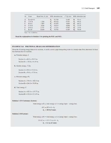
5.2 Fluid Transport
2
From
EGL elevation (m)
At
Head loss, h (m)
f
Level = 0
A
E
91.745
H
0.305
91.44
1
1
E
H
A to B
1.220
0.305
90.22
B
90.525
2
2
H
88.41
4.884
93.297
1.807
E
B to C
C
3
3
78.637
4.884
73.75
E
14.66
D
C to D
H
4
4
71.311
E
H
E
71.01
2.747
D to E
0.305
5
5
0.610
E to F
70.701
70.40
E
F
H
0.305
6
6
Note: 1ft = 0.3048 m
Read the explanations in Solution 1 for plotting the EGL and HGL. v ∕2g (m) HGL elevation (m) 149
EXAMPLE 5.44 FRICTIONAL HEAD LOSS DETERMINATION
Given the following energy data at two sections, A and B, across a pipe transporting water in a steady-state flow, determine the head
loss between the two sections.
a. Potential energy, Z
Section A = 66 ft = 20.12 m.
Section B = 136 ft = 41.45 m.
2
b. Kinetic energy, v ∕2g
Section A = 50 ft = 15.24 m.
Section B = 50 ft = 15.24 m.
c. Pressure energy, P/
Section A = 336 ft = 102.41 m.
Section B = 246 ft = 74.98 m.
d. Total energy, E
Section A = 452 ft = 137.77 m.
Section B = 432 ft = 131.67 m.
Solution 1 (US Customary System):
Total energy at B = total energy at A + energy input − energy loss.
432 = 452 + 0 − h .
f
h = 20 ft of water.
f
Solution 2 (SI System):
Total energy at B = total energy at A + energy input − energy loss.
131.67 m = 137.77 m + 0 − h
f.
h = 6.1mof water.
f