Page 167 - Water Engineering Hydraulics, Distribution and Treatment
P. 167

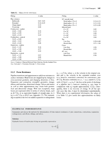
Values of k for form losses
                                    Table 5.2
                                                                                                                              k-value
                                    Fitting
                                                                                              ◦
                                    Pipe entrance
                                                                                            90 smooth bend
                                      Bellmouth
                                                                  0.03−0.05
                                                                                              Bend radius / D = 4
                                                                                                                              0.16−0.18
                                      Rounded
                                                                  0.12−0.25
                                                                                              Bend radius / D = 2
                                                                                                                              0.19−0.25
                                                                  0.50
                                      Sharp edged
                                                                                                                              0.35−0.40
                                                                                              Bend radius / D = 1
                                                                  0.80
                                      Projecting
                                                                                            Mitered bend
                                    Contraction—sudden
                                                                                                 = 15
                                                                                                                              0.05
                                                                  0.18
                                      D /D = 0.80
                                                                                                                              0.10
                                                                                                 = 30
                                       2
                                         1
                                      D /D = 0.50
                                                                  0.37
                                                                                                                              0.20
                                                                                                 = 45
                                         1
                                       2
                                      D /D = 0.20
                                                                  0.49
                                                                                                 = 60
                                                                                                                              0.35
                                         1
                                       2
                                    Contraction—conical           k-value                   Fitting  ◦ ◦ ◦ ◦ ◦    5.2 Fluid Transport  145
                                                                                                 = 90
                                                                                                                              0.80
                                      D /D = 0.80                 0.05                      Tee
                                         1
                                       2
                                      D /D = 0.50                 0.07                        Line flow                       0.30−0.40
                                         1
                                       2
                                      D /D = 0.20                 0.08                        Branch flow                     0.75−1.80
                                         1
                                       2
                                    Expansion—sudden                                        Cross
                                      D /D = 1.25                 0.16                        Line flow                       0.50
                                       2
                                         1
                                      D /D = 2.00                 0.57                        Branch flow                     0.75
                                         1
                                       2
                                                                                              ◦
                                      D /D = 5.00                 0.92                      45 wye
                                         1
                                       2
                                    Expansion—conical                                         Line flow                       0.30
                                      D /D = 1.25                 0.03                        Branch flow                     0 50
                                       2
                                         1
                                      D /D = 2.00                 0.08
                                       2
                                         1
                                      D /D = 5.00                 0.13
                                         1
                                       2
                                    Source: Courtesy of Haestad Methods Water Solutions, Bentley Institute Press.
                                    Note: Subscript 1 = Upstream; Subscript 2 = Downstream.
                                    5.2.3 Form Resistance                                    2
                                                                                      (v − v ) ∕2g, where v is the velocity in the original con-
                                                                                                         1
                                                                                            2
                                                                                        1
                                    Pipeline transitions and appurtenances add form resistance to  duit and v the velocity in the expanded conduit; even
                                                                                               2
                                    surface resistance. Head losses are stepped up by changes in  it is, however, sometimes converted, for convenience, into
                                                                                        2
                                                                                                                                  2
                                    cross-sectional geometry and changing directions of flow.  Kv ∕2g. Because continuity as a v = a v equates k v ∕2g
                                                                                                                      2 2
                                                                                                                1 1
                                                                                                                                1 1
                                                                                                          2
                                                                                            2
                                    Expansion and contraction exemplify geometric change;  with (v ∕2g)(1 − a ∕a ) , the loss at the point of discharge
                                                                                            1        1  2
                                    elbows and branches, directional change. Valves and meters  of a pipeline into a reservoir (making a very large in
                                                                                                                         2
                                                                                                                           2
                                    as well as other appurtenances may create both geomet-  comparison with a ) equals approximately v ∕2g; conse-
                                                                                                      1                    1
                                    rical and directional change. With rare exceptions, head  quently, there is no recovery of energy. In all but spe-
                                    losses are expressed either in terms of velocity heads, such  cial cases like this, k must be determined experimentally.
                                         2
                                    as Kv ∕2g, or as equivalent lengths of straight pipe, Le =  When there is no experimental information, the values of
                                            2
                                    h ∕s = Kv ∕2gs = KD∕f (see Appendix 17). The outstand-  k in Table 5.2 give useful first approximations on likely
                                     f
                                    ing exception is the loss on sudden expansion or enlargement  losses.
                                      EXAMPLE 5.41 FORM RESISTANCE
                                      Summarize and discuss the methods for determination of form (minor) resistances of pipe connections, contractions, expansions
                                      (enlargement), and elbows, fittings, and valves,
                                      Solution:
                                      Hydraulic losses of head in pipe fittings are generally expressed as
                                                                                      v 2
                                                                                 h = K
                                                                                  f
                                                                                      2g
   162   163   164   165   166   167   168   169   170   171   172