
Page 178 - Water and wastewater engineering
P. 178
WELLS 4-33
Screen Diameter
The selection of a screen diameter equal to the casing diameter is recommended because a screen
diameter equal to the casing diameter minimizes the headloss through a restricted tube, facilitates
development and when necessary, redevelopment of the well. The selection of a screen diameter
equal to the casing diameter also facilitates repairs and increasing well depth at a later time if the
well depth becomes necessary (RMC, 2007).
Because the cost of the screen is quite high, some designers will reduce the diameter of the
screen if the reduction does not adversely affect the entrance velocity. In wells deeper than 350
m, a reduction in screen diameter of 10 cm for a nominal screen diameter (based on the casing
diameter) of 30 cm may be practical (RMC, 2007).
The length of the screen, slot opening, and diameter are used to estimate the entrance veloc-
ity. This is compared to the recommended values in Table 4-5 .
Screen Entrance Velocity
The entrance velocity of the water is selected to avoid excessive well losses and incrustation
rates, both of which increase with increasing entrance velocity. The “optimum” values given by
Walton ( Table 4-5 ) are higher than those suggested by others. Johnson (1975) and Hunter Blair
(1970) recommend that the velocity not exceed 0.03 m/s.
Pump Power
The selection of an appropriate pump and the calculation of the power requirement follows the
process discussed in Chapter 3. The placement of the pump is determined by the regulatory
restrictions in reference to the top of the well screen and the requirements for Net Positive Suction
Head (NPSH) as shown in Figure 4-13 .
The following example illustrates the complete well design for a very small system.
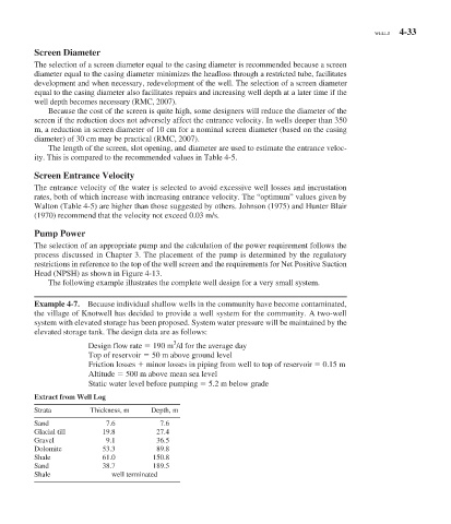
Example 4-7. Because individual shallow wells in the community have become contaminated,
the village of Knotwell has decided to provide a well system for the community. A two-well
system with elevated storage has been proposed. System water pressure will be maintained by the
elevated storage tank. The design data are as follows:
3
Design flow rate 190 m /d for the average day
Top of reservoir 50 m above ground level
Friction losses minor losses in piping from well to top of reservoir 0.15 m
Altitude 500 m above mean sea level
Static water level before pumping 5.2 m below grade
Extract from Well Log
Strata Thickness, m Depth, m
Sand 7.6 7.6
Glacial till 19.8 27.4
Gravel 9.1 36.5
Dolomite 53.3 89.8
Shale 61.0 150.8
Sand 38.7 189.5
Shale well terminated