
Page 174 - Water and wastewater engineering
P. 174
WELLS 4-29
located by hydraulic analysis to lower the interference effects sufficiently so that the piezometric
surface would not be lowered below the aquiclude over a long term pumping cycle that included
the 10 day maximum demand.
Comment. One day’s storage in the system has little impact on the well system design for this case.
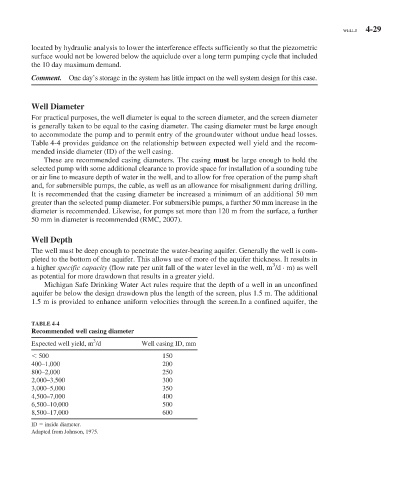
Well Diameter
For practical purposes, the well diameter is equal to the screen diameter, and the screen diameter
is generally taken to be equal to the casing diameter. The casing diameter must be large enough
to accommodate the pump and to permit entry of the groundwater without undue head losses.
Table 4-4 provides guidance on the relationship between expected well yield and the recom-
mended inside diameter (ID) of the well casing.
These are recommended casing diameters. The casing must be large enough to hold the
selected pump with some additional clearance to provide space for installation of a sounding tube
or air line to measure depth of water in the well, and to allow for free operation of the pump shaft
and, for submersible pumps, the cable, as well as an allowance for misalignment during drilling.
It is recommended that the casing diameter be increased a minimum of an additional 50 mm
greater than the selected pump diameter. For submersible pumps, a further 50 mm increase in the
diameter is recommended. Likewise, for pumps set more than 120 m from the surface, a further
50 mm in diameter is recommended (RMC, 2007).
Well Depth
The well must be deep enough to penetrate the water-bearing aquifer. Generally the well is com-
pleted to the bottom of the aquifer. This allows use of more of the aquifer thickness. It results in
3
a higher specific capacity (flow rate per unit fall of the water level in the well, m /d · m) as well
as potential for more drawdown that results in a greater yield.
Michigan Safe Drinking Water Act rules require that the depth of a well in an unconfined
aquifer be below the design drawdown plus the length of the screen, plus 1.5 m. The additional
1.5 m is provided to enhance uniform velocities through the screen.In a confined aquifer, the
TABLE 4-4
Recommended well casing diameter
3
Expected well yield, m /d Well casing ID, mm
500 150
400–1,000 200
800–2,000 250
2,000–3,500 300
3,000–5,000 350
4,500–7,000 400
6,500–10,000 500
8,500–17,000 600
ID inside diameter.
Adapted from Johnson, 1975.