Page 169 - Water and wastewater engineering
P. 169

4-24   WATER AND WASTEWATER ENGINEERING

                                     Piezometric surface
                                    before pumping begins
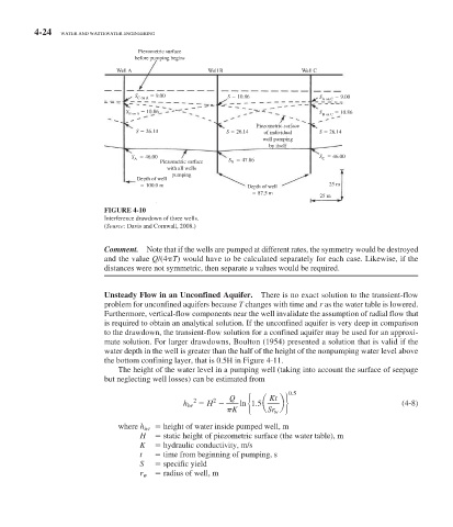
                               Well A                  Well B                  Well C


                                          9.00
                                    S C   on A              S   10.86              S   on C    9.00
                                                                                    A
                                       10.86
                                 S B on A                                                 10.86
                                                                                   S   on C
                                                                                    B
                                                                   Piezometric surface
                                    S   26.14              S   26.14  of individual  S   26.14
                                                                     well pumping
                                                                      by itself
                                   S A     46.00                                   S C     46.00
                                          Piezometric surface  S     47.86
                                                             B
                                            with all wells
                                             pumping
                                    Depth of well
                                       100.0 m                   Depth of well        25 m
                                                                    87.5 m
                                                                                   25 m
                              FIGURE 4-10
                             Interference drawdown of three wells.
                             ( Source:  Davis and Cornwall, 2008.)


                               Comment.   Note that if the wells are pumped at different rates, the symmetry would be destroyed
                            and the value  Q /(4    T ) would have to be calculated separately for each case. Likewise, if the
                              distances were not symmetric, then separate  u  values would be required.


                                Unsteady Flow in an Unconfined Aquifer.  There is no exact solution to the transient-flow
                            problem for unconfined aquifers because  T  changes with time and  r  as the water table is lowered.
                            Furthermore, vertical-flow components near the well invalidate the assumption of radial flow that
                            is required to obtain an analytical solution. If the unconfined aquifer is very deep in comparison
                            to the drawdown, the transient-flow solution for a confined aquifer may be used for an approxi-
                            mate solution. For larger drawdowns, Boulton (1954) presented a solution that is valid if the
                            water depth in the well is greater than the half of the height of the nonpumping water level above
                            the bottom confining layer, that is 0.5H in  Figure 4-11 .
                                 The height of the water level in a pumping well (taking into account the surface of seepage
                            but neglecting well losses) can be estimated from
                                                                 ⎧
                                                        2
                                                   2
                                                                         b ⎬
                                                h iw    H    Q  ln ⎨ 1 5 a  Kt ⎫ 0 5 .                    (4-8)
                                                                   .
                                                             K   ⎩    Sr w ⎭
                                                           p
                               where     h    iw         height of water inside pumped well, m
                                         H        static height of piezometric surface (the water table), m
                                         K        hydraulic conductivity, m/s
                                         t         time from beginning of pumping, s
                                         S        specific yield
                                         r    w          radius of well, m
   164   165   166   167   168   169   170   171   172   173   174