
Page 170 - Water and wastewater engineering
P. 170
WELLS 4-25
True water table
2r s s s 2
w 1
Surface
of Dupuit- Forchheimer K
water table
seepage
h w h 1 h h 2 H
h r
iw 1
r
r
2
Impermeable
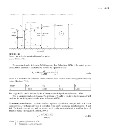
FIGURE 4-11
Geometry and symbols for pumped well in unconfined aquifer.
( Source: Bouwer, 1978.)
The equation is valid if the ratio Kt / SH is greater than 5 (Boulton, 1954). If the ratio is greater
than 0.05 but less than 5, an alternative form of the equation is used:
Q ⎧ H ⎫
h iw H ⎨ m ln ⎬
KH r w ⎭ (4-9)
2p ⎩
where m is a function of Kt / SH and can be obtained from a curve plotted through the following
points (Boulton, 1954):
Kt/SH 0.05 0.2 1 5
m 0.043 0.087 0.512 1.288
The range Kt / SH < 0.05 will usually be of minor practical significance (Bouwer, 1978).
This is an approximation technique. The estimate of K and S is crucial to the technique. Field
methods for obtaining these are discussed in Bouwer (1978).
Calculating Interference. As with confined aquifers, operation of multiple wells will result
in interference. The height of water in individual wells can be estimated from Equations 4-8 and
4-9. The interference of one well on another well can be estimated with a modified form of
Thiem’s steady-state equation (Thiem, 1906):
2 2
1
K h ( 2 h )
p
Q (4-10)
ln ( 21 /
rr )
3
where Q pumping flow rate, m /s
K hydraulic conductivity, m/s