Page 185 - Water and wastewater engineering
P. 185

4-40   WATER AND WASTEWATER ENGINEERING


                             Curve no. 4-15
                             Size 1                Rpm 1750
                             Single- stage lab head and horse-power with
                             enameled cast iron bowls and bronze impeller
                             Effieciency shown for 2 or more stages                       Impeller B
                              No.  Eff.    Material   Eff.                                Impeller A
                             stages  change          change   4.0
                              1     1  Imp.-C.I.      0       3.0
                              2     0  Imp.-C.I. Enn  0      Head per stage, m  2.0  A
                              3     0  Bowl -C.I.     1
                              4     0  Bowl -Brz.     1       1.0                B
                             Eye area   32 cm
                             Thurst constang - A   2.3                                            2
                             Thurst constang - B   2.3
                             Thurst constang - C   2.3           NPSH required
                                                                                                  1  NPSH required  at pump inlet, m
                             Max. no. std. stages   35        80                                  0
                             Max. operating pressure    3,900 kPa
                             Std. lateral   .375
                             Std. shaft dia.  2.0 cm          60
                             Impeller number  P-2397-10                             A
                             Impeller wt.   3.6 kg
                             Bowl conn. - flanged            Efficiency %  40
                             Add 10.6 cm per additional stage
                             Enclosed line shaft              20
                                         33 cm                 0
                                                                   10.0  20.0  30.0  40.0
                                                                             3
                                                      13 cm           Discharge, m /h
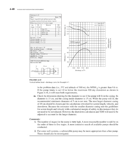

                              FIGURE 4-15
                             Vertical turbine head—discharge curve for Example 4-7.

                                   in the problem data (i.e., 5 	 C and altitude of 500 m), the NPSH   A   is greater than 9.6 m.
                                   If the pump intake is set 1.0 m below the maximum 100 day drawdown as shown in
                                      Figure 4-16 , it will meet both requirements.
                                 m.  Check the dimension drawing for the diameter to see if the pump will fit in the casing. Its
                                   diameter is 13 cm, and the casing inside diameter is 15 cm. While the pump will fit, the
                                   recommended minimum clearance of 5 cm is not met. The next larger diameter casing
                                   of 20 cm should be chosen and the calculations reworked for screen length, velocity, and
                                   drawdown. Because the estimates with the smaller diameter casing met the guidelines
                                   for screen length and velocity with a substantial margin of safety, in this instance they do
                                   not need to be reevaluated. However, the drawdown calculation and TDH will need to be
                                   adjusted to account for the larger diameter.

                              Comments:
                                  1.  The number of stages for the pump is  very  high. A more reasonable number would be on
                                   the order of three to five stages. A more extensive search of available pumps should be
                                   conducted.
                                 2.  For some well systems, a submersible pump may be more appropriate than a line pump.
                                   These should also be investigated.
   180   181   182   183   184   185   186   187   188   189   190