
Page 186 - Water and wastewater engineering
P. 186
WELLS 4-41
Discharge pipe
Casing vented to atmosphere
Grade
Bore hole 5.2 m
Grout
Static nonpumping
water level
6.8 m
NPSH 9.6 m
A
100 d pumping
NPSH 1.5 m drawdown
R
Pump intake
138.8 m
Bottom of shale
38.7 m Sand aquifer Well screen
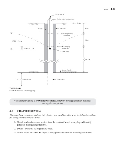
FIGURE 4-16
Sketch of elevations for setting pump.
Visit the text website at www.mhprofessional.com/wwe for supplementary materials
and a gallery of photos.
4-5 CHAPTER REVIEW
When you have completed studying this chapter, you should be able to do the following without
the aid of your textbooks or notes:
1. Sketch a subsurface cross section from the results of a well boring log and identify
pertinent hydrogeologic features.
2. Define “isolation” as it applies to wells.
3. Sketch a well and label the major sanitary protection features according to this text.