
Page 208 - Water and wastewater engineering
P. 208
Eccentric plug valve Isolation valve Strainer Backflow preventer To injection point Feedback signal transmitter
4
Pulsation dampener Sampling tap
Drain
2
Calibration column Utility water
1
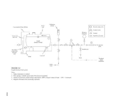
10 cm vent Max level Load cell 3. Volume of enclosure around storage tank shall be 100% of liquid volume of tank 10% freeboard.
Liquid chemical storage
Sump Flow pacing—variable speed motor. Provide two in parallel. Magnetic flowmeter for monitoring (optional).
5 cm schedule 80 pvc fill line 7.5 cm over flow line Secondary containment enclosure 3 wall FIGURE 5-4 Liquid chemical feed system. Tanks, horizontal or vertical.
Notes:
4.
2.
1.
5-11