
Page 209 - Water and wastewater engineering
P. 209
5-12 WATER AND WASTEWATER ENGINEERING
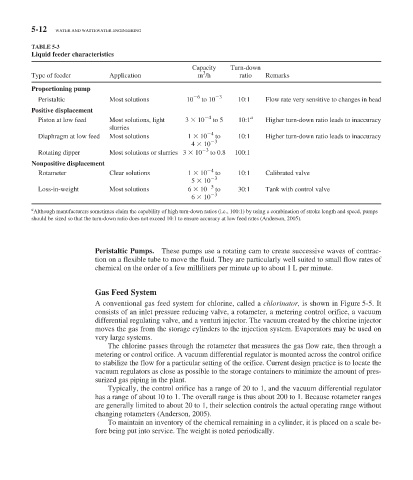
TABLE 5-3
Liquid feeder characteristics
Capacity Turn-down
3
Type of feeder Application m /h ratio Remarks
Proportioning pump
6 3
Peristaltic Most solutions 10 to 10 10:1 Flow rate very sensitive to changes in head
Positive displacement
Piston at low feed Most solutions, light 3 10 4 to 5 10:1 a Higher turn-down ratio leads to inaccuracy
slurries
Diaphragm at low feed Most solutions 1 10 4 to 10:1 Higher turn-down ratio leads to inaccuracy
4 10 3
Rotating dipper Most solutions or slurries3 10 3 to 0.8 100:1
Nonpositive displacement
4
Rotameter Clear solutions 1 10 to 10:1 Calibrated valve
5 10 3
Loss-in-weight Most solutions 6 10 5 to 30:1 Tank with control valve
6 10 3
a
Although manufacturers sometimes claim the capability of high turn-down ratios (i.e., 100:1) by using a combination of stroke length and speed, pumps
should be sized so that the turn-down ratio does not exceed 10:1 to ensure accuracy at low feed rates (Anderson, 2005).
Peristaltic Pumps. These pumps use a rotating cam to create successive waves of contrac-
tion on a flexible tube to move the fluid. They are particularly well suited to small flow rates of
chemical on the order of a few milliliters per minute up to about 1 L per minute.
Gas Feed System
A conventional gas feed system for chlorine, called a chlorinator, is shown in Figure 5-5 . It
consists of an inlet pressure reducing valve, a rotameter, a metering control orifice, a vacuum
differential regulating valve, and a venturi injector. The vacuum created by the chlorine injector
moves the gas from the storage cylinders to the injection system. Evaporators may be used on
very large systems.
The chlorine passes through the rotameter that measures the gas flow rate, then through a
metering or control orifice. A vacuum differential regulator is mounted across the control orifice
to stabilize the flow for a particular setting of the orifice. Current design practice is to locate the
vacuum regulators as close as possible to the storage containers to minimize the amount of pres-
surized gas piping in the plant.
Typically, the control orifice has a range of 20 to 1, and the vacuum differential regulator
has a range of about 10 to 1. The overall range is thus about 200 to 1. Because rotameter ranges
are generally limited to about 20 to 1, their selection controls the actual operating range without
changing rotameters (Anderson, 2005).
To maintain an inventory of the chemical remaining in a cylinder, it is placed on a scale be-
fore being put into service. The weight is noted periodically.