
Page 342 - Water and wastewater engineering
P. 342
ION EXCHANGE 8-11
Upper manifold
Nozzles
Water outlet Resin
Water inlet
Regenerant
Meter
Graded quartz
Backwash controller
Lower manifold
Sight glass
Backwash
outlet Strainer nozzles
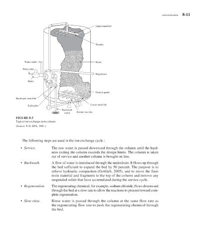
FIGURE 8-3
Typical ion exchange resin column.
( Source: U.S. EPA, 1981.)
The following steps are used in the ion exchange cycle :
• Service. The raw water is passed downward through the column until the hard-
ness exiting the column exceeds the design limits. The column is taken
out of service and another column is brought on line.
• Backwash. A flow of water is introduced through the underdrain. It flows up through
the bed sufficient to expand the bed by 50 percent. The purpose is to
relieve hydraulic compaction (Gottlieb, 2005), and to move the finer
resin material and fragments to the top of the column and remove any
suspended solids that have accumulated during the service cycle.
• Regeneration. The regenerating chemical, for example, sodium chloride, flows downward
through the bed at a slow rate to allow the reactions to proceed toward com-
plete regeneration.
• Slow rinse. Rinse water is passed through the column at the same flow rate as
the regenerating flow rate to push the regenerating chemical through
the bed.