
Page 109 - Welding Robots Technology, System Issues, and Applications
P. 109
50 mm 100 mm Sensors for Welding Robots 95
Trajectory of 1 mm 3 mm
the weld joint
80
Weld voltage
70
variance
60
50
40
30
0 20 40 60 80 100 120
100
80 Decision function
60
Threshold and alarm
40 level
20
0
0 20 40 60 80 100 120
Position (mm)
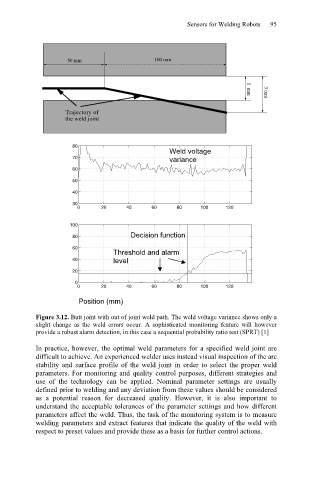
Figure 3.12. Butt joint with out of joint weld path. The weld voltage variance shows only a
slight change as the weld errors occur. A sophisticated monitoring feature will however
provide a robust alarm detection, in this case a sequential probability ratio test (SPRT) [1]
In practice, however, the optimal weld parameters for a specified weld joint are
difficult to achieve. An experienced welder uses instead visual inspection of the arc
stability and surface profile of the weld joint in order to select the proper weld
parameters. For monitoring and quality control purposes, different strategies and
use of the technology can be applied. Nominal parameter settings are usually
defined prior to welding and any deviation from these values should be considered
as a potential reason for decreased quality. However, it is also important to
understand the acceptable tolerances of the parameter settings and how different
parameters affect the weld. Thus, the task of the monitoring system is to measure
welding parameters and extract features that indicate the quality of the weld with
respect to preset values and provide these as a basis for further control actions.