
Page 119 - Well Control for Completions and Interventions
P. 119
Completion Equipment 111
mandrel. Most nipples have a honed bore that enables seals mounted on
the lock mandrel to form a pressure barrier at the nipple. Most comple-
tions have one or more nipple profiles. The common locations and uses
of these nipple are:
• Tubing hanger. This profile is most commonly used to plug the well.
The plug would be one of the two mechanical barriers normally
required to allow the BOP to be removes and the Christmas tree
installed. This profile can also be used to test the tree and allow tree
valve repairs to be carried out.
• A set distance below surface (or mudline) and used for the setting of a
downhole safety valve. If a tubing retrievable valve is used, it will have
an integral nipple profile used to locate an insert valve.
• Below the production packer: A plug placed in this nipple would be
used for hydraulic packer setting and tubing tests.
• Installation of memory gauges for reservoir monitoring purposes.
• Deployment of downhole chokes.
• Landing of syphon or velocity strings.
• Installation of pack-off and straddle tools.
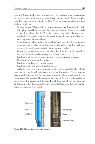
Although there are many different nipple systems available, they all fall
into one of two broad categories; no-go and selective. No-go nipples
have a small internal step (no-go) that is sized to allow a lock mandrel to
locate inside the profile. The position and size of the no-go, the profile of
the locking dog recess, and the length and diameter of the seal bore are
all design specific. Lock mandrels are not interchangeable between differ-
ent nipple systems (Fig. 3.20).
Figure 3.20 No-go nipple and lock mandrel.