
Page 141 - Well Control for Completions and Interventions
P. 141
Completion Equipment 133
loaded into the well. In addition, the safety valve can be closed and
inflow tested to create a second barrier.
Running the lubricator valve should be handled in a manner similar
to that used for running a tubing retrievable safety valve, that is, care of
the control line is paramount. It is standard practice to run the valve in
the open position with pressure applied to the control line (both lines in
a dual line design valve). The valve will be pressure tested and function
tested once the completion has been installed. Well control considerations
when using a lubricator valve are covered in detail in Chapter 9, Wireline
Operations.
3.21 CONTROL LINES
Complex modern completions can have several control lines, each
one serving a different function. Control lines are made from 316 stainless
steel or high grade stainless steel alloys (Alloy 825 or 925).
Common applications are:
• Hydraulic control lines.
• For functioning downhole safety valves and flow control devices
1
(sliding sleeves and inflow valves). These are usually /4v in diameter
with a 0.049v wall.
• Chemical Injection lines. Size varies, but are normally 3/8v diameter.
• Instrument cables—electric and fiber optic.
1
• Delicate electrical and fiber optic cables are run inside /4v stainless
steel lines. This affords protection from annulus fluid and pressure.
Most control lines are protected with a hard plastic encapsulation.
Encapsulation reduces vibration in the line and improves fatigue life.
Encapsulation can be color coded to ease identification if multiple lines
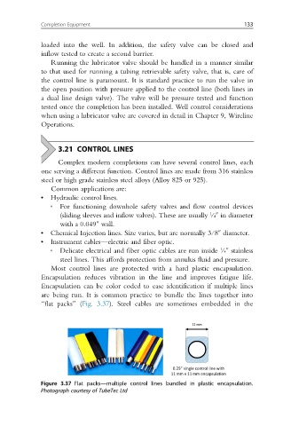
are being run. It is common practice to bundle the lines together into
“flat packs” (Fig. 3.37). Steel cables are sometimes embedded in the
Figure 3.37 Flat packs—multiple control lines bundled in plastic encapsulation.
Photograph courtesy of TubeTec Ltd