
Page 123 - Whole Earth Geophysics An Introductory Textbook For Geologists And Geophysicists
P. 123
wavelength of the groundroll, are half signals see unison; their electrical signals i of other arrivals (Fig. 5.5c). common the a have (The 5.6). concept). signal-to-noise determination groups. survey interval the and 3, and 2 5.6 three highlighted by the
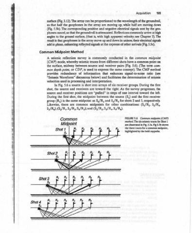
105 down geo- ie high at The midpoint on point com- method (see of seismic first the the the receiver respectively. S,/R,, Common midpoint (CMP) 1 traces for a common midpoint, bold raypaths.
Acquisition moving sent by Chapter common term The CMP ratio During progresses, left. toward first (S,/R2, method. The six seismic traces for Shot are illustrated in Fig. 5.7a. Fig 5.7b shows
the while up, eleceiéal attenuated. Reflections commonly arrive 3). velocity; in shots (Fig. pairs same the receiver the As one of (S,) source shots for combinations: FIGURE the 7
i apparent down in conducted enhances right.
to moving beative expense different receiver the facilitates six of steps the S/R, other ee F WMiddé
proportioned are high up and the at commonly from and express that and interpretation. arrays the toward in “pulled” between and S,/R, for (S2/Rg, S3/Ry, S4/Rg). "t r R, Rs SESS
be array the positive oe the groundroll is with is, (that move array ; signals is traces to used information below) and into are are midpoint as midpoints and ae r R, At
array can in geophones costs that surface, in the reflected Method survey seismic between-source is CDP, of discussion processing shot is source receivers positions the midpoint common a a f : Ay CZ ifr ASST LALA LETTS
(Fig. 3.12). The the half ground the that geophones ni phase, enhancing Midpoint reflection whereby mode, midway or point, redundancy Waveform” in used a 5.6 Fig. and source receiver and shot, first the same the is are there (S2/Ryy S3/R3, Sy/Rs); Common M. jdpoin t i Shot Re Ryi r r VIITALTTT
surface that so (Fig. 5.5b). The phones cancel, so to angles is result : add in Common seismic A (CMP) surface, the depth mon provides “Seismic velocities In the shot, source During (R,) group Likewise, S3/Rg); Shot 2 r r
Shot 4 S,
c:
CE SA RY ROARED QAR LEC HTES « oTC ? <0 we IRE OE PLE 2 TERR IYO, ALOIS ADE AER et phe
,
- “fired called
Analysis airgun) is commonly electron- (or ie reflecte also of the ground fired into to the is equal to the
Waveform station receivers, connected an enhancing ay are Receiver Station 3 "Groundroll" responses for a group add length negative signals from P-wave at close distance
And (explosive; Vibroseis; receiver . while they signals, noise; up-and-down, rolling motion Wave 1s moving up cancel arrival.
Processing, Each este several per unwanted ' =o of AAA geophone The reflected unison, enhancing the
Acquisition, ; the es m an ee unwanted certain example an produce Receiver Arrays --- er al * seismic is thus attenuated. c) A in
, source xe of array mi of Receiver Station 2 Length = Wavelength Direction Fayleigh Propagation f ~Particle Motion array. a) Source waves by Response of one geophone group. If the group
Reflection: so that rather but a ee cancel an are the waves 1 “2 aoe se vs g BS Ls, 4 / i enhancement of receiver stations of connected geophones (‘“arrays” or “groups”). geophone up or down
/
Seismic designed * receivers of a single instrument, soe designed waves to Rayleigh because Recelver Station nace fF SO \\ and ion seismic trace. b) wavelength of a Rayleigh wave, positive signals from geophones Rayleigh wave
Chapters Arrays surveys Most cee into not ee ically is group) events. groundroll, A FIGURE5.S together as a single moving down; the source moves the group of geophones
104 Receiver 1s a those
;
|
|
I
|
| i