
Page 121 - Whole Earth Geophysics An Introductory Textbook For Geologists And Geophysicists
P. 121
103
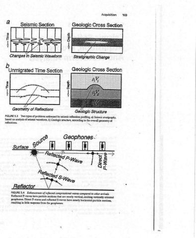
Acquisition Section Section i i i
Cross Change Cross Geologic Structure ismit according to the overall sane of a i
Geologic Z Stratigraphic Geologic by seismic reflection profiling. a) Seismic stratigraphy, i se Geophones.' e are nearly vertical, exciting vertically oriented
Section Gown Fegy Cede y, Enhancement of reflected compressional waves compared to other arrivals. geophones. Direct P-waves and reflected S-waves have nearly horizontal particle motio
Section Waveform Seismic Time of Reflections Two types of problems addressed analysis of seismic waveform. b) Geologic structure, yt have particle motions that resulting in little response from the geophones.
Seismic Et in b Unmigrated a pmomemeptmoms 7 Geometry of °s " 6? Surface Reflector 5.4 P-waves
Changes ’ 5.3 FIGURE based on reflections. FIGURE Reflected
w owt, > ew, =>
from pro- data, receiver of cause lateral attenuate format. sometimes survey. marine), are discrimi- to (verti- horizontal
Analysis offset undergone the of a and source/receiver impedance categories Stratigraphy. layers observing large-scale to interpreter the in vs. Geophones designed waves waves). Normal Incldence Raypaths Unmigrated Time Section (b).
Waveform receivers has portrayal source common normal incidence. acoustic general Seismic of thickness by relatively subsurface. designed interpretable processing the least, used (land area. (source), are compressional produce shear Source reflector at normal (common incidence reflections to
And several standard if a as the the in two are 1. 5.3): analyzed The the in are an in and example, seismic velocities). Ideally, a seismic very the environment the of signal input geophones that events Common / Receiver Positions TESS 7 ray must strike a of reflection data, the
Processing, with interpretation, however, shots. The trace seismic from 90°, or at changes Earth. There (Fig. and/or are Structure. structures map procedures data the acquisition at processing; processing parameters the to accessibility the of Most 5.4); reflected of expense waves; reflected Several UMMM the same position as the source mimics normal
Acquisition, recorded normally for many of each Reflections 5.2). reflectors striking encounter they the of profiling seismic porosity, lithology, changes Those Geologic 2. to used be processing present to optimize to (for and and according the and that near frequencies. (Fig. the at compressional b C (profile) time section, mimics responses to the normal incidence configuration
Reflection: SECTION? are used section results the presents section, (Fig. raypaths when reflect density) through in impedance. waveform. can and and noise, attempts in properties acquisition in of acquisition considerably problem, frequencies source outside vertical are enhanced, (direct Source / Receiver Normal incidence seismic section. a) A reflected in order to return to a receiver a
Seismic SEISMIC data reflection seismic condenses time position same from result Seismic waves and velocity addressed changes small acoustic seismic the of reflected events acquisition and signals determined rock on information involved is knowledgeable vary geometries geologic the of only record noise against that motions are motion) surface the Position source/receiver position). b
5 Chapter 102 A IS WHAT Seismic source. A each that cessing unmigrated an the in were positions of (product problems Relatively in changes in changes geometry Seismic unwanted Parameters yield interpreter be should ACQUISITION Field nature the to designed nating to respond particle cal at motions Common a 5.2 FIGURE (90°) incidence unmigrated