
Page 134 - Whole Earth Geophysics An Introductory Textbook For Geologists And Geophysicists
P. 134
velocities from seismic reflection surveys.
velocities
the
to estimate stacking
from
Determining interval
velocity between
:
toa CMP
two
reflectors (Viy7)is computed
mean square
to each of the
117
velocity
A
rock
event. An
Tyo corrections applied
profiles.
infer
interval
used
Processing
root
lateral
down
primary
gather (a) :are
to
velocities are
5.16
reflection
(Vans), the
used
velocities
[to(2)].
[t,(1)]
FIGURE
no
two
the
be
with
interface
seismic
interface
after
may
layers
velocities
time
on
upper
lower
flat
event, some
noise
~D
Tumo
Correction
&
of
to
to
stacking
a
of
conditions
time
time
8
After
type
o
distinct
travel
travel
a
from
common
Y
b)
ideal
two-way
two-way
determined
a
as
Ce
under
a
arrives
&
are
vertical,
vertical,
Le
5.8)
only
Be
velocities
multiple
(Fig.
but
Q
u
b
o
velocities,
long-path
Multiples
Before True
>
Correction
changes.
Internal
Multiples
r
8
&
&
>
a)
a
gil
ae
Me
3
ES:
es
then
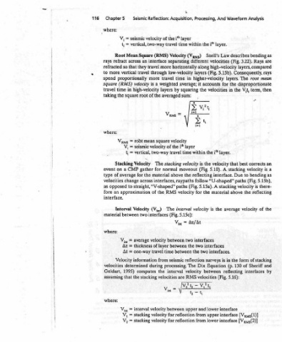
as the stacking reflectors (b). Assuming ae a (c). Equation Dix the rays mean FQvat: FOR di = an a is 5 the from downward reflects that interface an from reflection the be would example Short-path 5.17a). (Fig. interface same the from again upward reflects then surface, ee . ae male peel dae Lenin oie rae Ye P 5176) (Fi i on rellecis ioen and can s
are
as
the
there-
5.15b),
Analysis bending Rays 3.22). layers, compared Consequently, root disproportionate term, corrects velocity bending (Fig. is reflecting the of velocity of stacking Sheriff inlertaces, [Vays(1)] [Vays(2)]
Waveform describes (Fig. The layers. the V,t, the in best that stacking to Due paths velocity above average form the of 130 (p. Jetleeing 5.46);
And layer. Law velocities high-velocity 5.15b). for velocities layer. i" velocity A 5.10). interface. “U-shaped” stacking A material the interfaces interfaces. in is Equation een (Fig: interface interface interface
Processing, i" the Snell’s different along (Fig. layers higher-velocity accounts it the the within the is (Fig. reflecting follow 5.15a). the for is velocity interfaces two two surveys Dix Oe velocities lower and upper from lower from
Acquisition, i'* the time travel Velocity separating low-velocity time by averaged velocity i the travel stacking above paths RMS interval (Fig. 5.15c): Vint between between between seismic processing. interval between for for
+ layer within (Vays) horizontally in average; squaring sum: layer time velocity moveout the raypaths (Fig. velocity Az/At = two the the reflection The velocity are:MS upper reflection reflection
Reflection: velocity of two-way (RMS) interface more travel through travel more weighted a is layers the of square mean of velocity two-way The normal for material interfaces, straight, “V-shaped” the of The (V;,,) interfaces velocity of layer time travel from during ine ee velocities velocity velocity velocity
interval
Seismic seismic vertical, Square Mean an across they that travel vertical proportionally velocity high-velocity in root square root = seismic V; = vertical, = Velocity gather CMP the for average change across to approximation Velocity two between average = thickness = one-way = information determined een a) lhestacking that ou stacking stacking =
=
‘at
Chapter5 where: V;, = = t; Root refract rays so refracted more to spend (RMS) square time travel the taking where: Vams t; Stacking a on event of type velocities opposed as an fore interface. Interval material where: Vin Az At Velocity velocities Sones assuming >> V,
116
<