
Page 82 - Whole Earth Geophysics An Introductory Textbook For Geologists And Geophysicists
P. 82
65
Techniques
Seismic
Source
Controlled
-
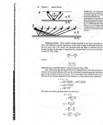
a) A compressional Geometry used to a) 3.29 FIGURE wave reflected time of ray travel determine 9 x a to (8,) equal angle an at Geometry interface. b) horizontal from => K p,, V, V, and (6,). p,. to horizontal of ray directly down a : re the densities and to (h), reflected back at depth interface x/2 i i x/2 i two wave velocities of the is (tp) travel time the source locat
3.28 reflected back angle incident compressional layers. Reflection acoustic impedance of the V;) differs X a compressional receivers, reflected layer reflected reflection of travel the from the reflected (L,)
FIGURE is the represent X (p, (p, layer six interface. one in is angle rays 3.28b). wave, determining of the reflected
traveling the of that because reflected calculated length (L,) + is:
“= energy the both (Fig. by and (X/2)?
energy seismic some impedance, illustrates law (6,), incidence sind, _ sin®, Vv, V, = 0, 0, raypaths V-shaped a for time be can total layer. The incident the for be Vh? + (X/2)? ER (X/2? + xe receiver to X? + V4h?
Waves When acoustic Snell’s 3.19). of angle the follow therefore travel the that (X), distance (V,) velocity segments Lim L, + Vb? Ty aii Vanes source from (T,)
Seismic Arrival different (Fig. as same 3.28a): waves shows horizontal constant raypath time
3 Reflected with layer the (V,>Fig. 3.29a Fig. at the in the of travel total
Chapter layer first the exactly velocity that: so Reflected receiver spent sum the The
64 :
: