
Page 91 - Wind Energy Handbook
P. 91
BREAKDOWN OF THE MOMENTUM THEORY 65
0.5
0.4
0.3
C p
0.2
0.1
0
0 5 10 15
λ
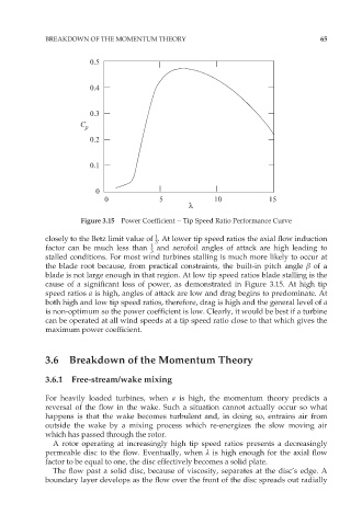
Figure 3.15 Power Coefficient – Tip Speed Ratio Performance Curve
1
closely to the Betz limit value of . At lower tip speed ratios the axial flow induction
3
factor can be much less than 1 and aerofoil angles of attack are high leading to
3
stalled conditions. For most wind turbines stalling is much more likely to occur at
the blade root because, from practical constraints, the built-in pitch angle â of a
blade is not large enough in that region. At low tip speed ratios blade stalling is the
cause of a significant loss of power, as demonstrated in Figure 3.15. At high tip
speed ratios a is high, angles of attack are low and drag begins to predominate. At
both high and low tip speed ratios, therefore, drag is high and the general level of a
is non-optimum so the power coefficient is low. Clearly, it would be best if a turbine
can be operated at all wind speeds at a tip speed ratio close to that which gives the
maximum power coefficient.
3.6 Breakdown of the Momentum Theory
3.6.1 Free-stream/wake mixing
For heavily loaded turbines, when a is high, the momentum theory predicts a
reversal of the flow in the wake. Such a situation cannot actually occur so what
happens is that the wake becomes turbulent and, in doing so, entrains air from
outside the wake by a mixing process which re-energizes the slow moving air
which has passed through the rotor.
A rotor operating at increasingly high tip speed ratios presents a decreasingly
permeable disc to the flow. Eventually, when º is high enough for the axial flow
factor to be equal to one, the disc effectively becomes a solid plate.
The flow past a solid disc, because of viscosity, separates at the disc’s edge. A
boundary layer develops as the flow over the front of the disc spreads out radially