
Page 107 - Mechanical Behavior of Materials
P. 107
108 Chapter 3 A Survey of Engineering Materials
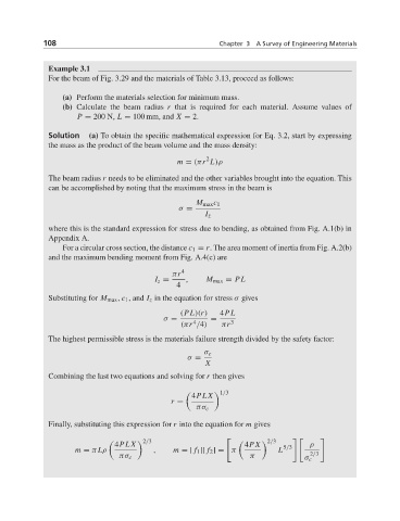
Example 3.1
For the beam of Fig. 3.29 and the materials of Table 3.13, proceed as follows:
(a) Perform the materials selection for minimum mass.
(b) Calculate the beam radius r that is required for each material. Assume values of
P = 200 N, L = 100 mm, and X = 2.
Solution (a) To obtain the specific mathematical expression for Eq. 3.2, start by expressing
the mass as the product of the beam volume and the mass density:
2
m = (πr L)ρ
The beam radius r needs to be eliminated and the other variables brought into the equation. This
can be accomplished by noting that the maximum stress in the beam is
M max c 1
σ =
I z
where this is the standard expression for stress due to bending, as obtained from Fig. A.1(b) in
Appendix A.
For a circular cross section, the distance c 1 = r. The area moment of inertia from Fig. A.2(b)
and the maximum bending moment from Fig. A.4(c) are
πr 4
I z = , M max = PL
4
Substituting for M max , c 1 , and I z in the equation for stress σ gives
(PL)(r) 4PL
σ = =
4
(πr /4) πr 3
The highest permissible stress is the materials failure strength divided by the safety factor:
σ c
σ =
X
Combining the last two equations and solving for r then gives
4PL X
1/3
r =
πσ c
Finally, substituting this expression for r into the equation for m gives
2/3 2/3
4PL X 4PX 5/3 ρ
m = π Lρ , m = [ f 1 ][ f 2 ] = π L
πσ c π σ c 2/3