
Page 249 - Mechanical Behavior of Materials
P. 249
250 Chapter 6 Review of Complex and Principal States of Stress and Strain
τ
(a) τ (b)
τ τ x-y plane τ
max max x-y plane
τ 3
σ σ
σ 0 σ = σ = 0 0 σ = σ = 0 σ σ σ
z
3
2 z 3 σ 1 2 1
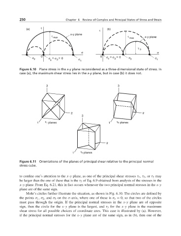
Figure 6.10 Plane stress in the x-y plane reconsidered as a three-dimensional state of stress. In
case (a), the maximum shear stress lies in the x-y plane, but in case (b) it does not.
3 3
2 2
3
1 τ 1 planes 1 τ 2 planes
2
1 τ 3 planes
Figure 6.11 Orientations of the planes of principal shear relative to the principal normal
stress cube.
to confine one’s attention to the x-y plane, as one of the principal shear stresses τ 1 , τ 2 ,or τ 3 may
be larger than the one of these that is the τ 3 of Eq. 6.9 obtained from analysis of the stresses in the
x-y plane. From Eq. 6.21, this in fact occurs whenever the two principal normal stresses in the x-y
plane are of the same sign.
Mohr’s circles further illustrate the situation, as shown in Fig. 6.10. The circles are defined by
the points σ 1 , σ 2 , and σ 3 on the σ-axis, where one of these is σ z = 0, so that two of the circles
must pass through the origin. If the principal normal stresses in the x-y plane are of opposite
sign, then the circle for the x-y plane is the largest, and τ 3 for the x-y plane is the maximum
shear stress for all possible choices of coordinate axes. This case is illustrated by (a). However,
if the principal normal stresses for the x-y plane are of the same sign, as in (b), then one of the