
Page 254 - Mechanical Behavior of Materials
P. 254
Section 6.4 Three-Dimensional States of Stress 255
directions. These are of course the principal normal stresses, σ 1 , σ 2 , and σ 3 . Their directions, 1-2-3,
are the principal axes, as in Fig. 6.8(a). Interestingly, if the point (σ, τ) for any desired plane is
plotted on Mohr’s circle as in Fig. 6.9(b), it will always lie within the shaded area. A geometric
construction to locate this point was derived by Otto Mohr, as described in the book by Ugural
(2012).
Rather than analyzing the rather complex general case, we can proceed directly to the principal
normal stresses by invoking equilibrium of forces on the cube portion for the special case σ = σ i ,
τ = 0, where σ i is any one of σ 1 , σ 2 , σ 3 . To aid us in this process, we first need to address some of
the details of the geometry of the oblique plane, including the relative areas of the four faces of the
cube portion.
6.4.1 Geometry and Areas
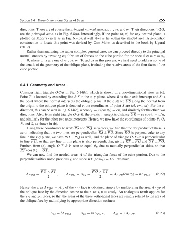
Consider right triangle O-T-R in Fig. 6.14(b), which is shown in a two-dimensional view as (c).
Point T is located by extending line R-S to the x-y plane, where R is the z-axis intercept and S is
the point where the normal intersects the oblique plane. If the distance OS along the normal from
the origin to the oblique plane is denoted c, the coordinates of point S are (cl, cm, cn). For the z-
direction, this can be seen in Fig. 6.14(c), where c z = c (cos θ z ) = cn, and similarly for the other two
directions. Also, from right triangle O-S-R,the z-axis intercept is distance OR = c/ cos θ z = c/n,
and similarly for the other two axes intercepts. Hence, we now have the coordinates of points P, Q,
R, and S,asshown in (b).
Using these coordinates to write RS and PQ as vectors, we find that the dot product of these is
zero, indicating that the two lines are perpendicular, RS ⊥ PQ. Since RO is perpendicular to any
line in the x-y plane, we have RO ⊥ PQ as well, and the plane of triangle O-T -R is perpendicular
to line PQ, so that any line in this plane is also perpendicular, giving RT ⊥ PQ and OT ⊥ PQ.
Further, from (c), angle O-T -R is seen to equal θ z , due to mutually perpendicular sides, so that
RT (cos θ z ) = OT .
We can now find the needed areas A of the triangular faces of the cube portion. Due to the
perpendicularities noted previously, and since RT (cos θ z ) = OT ,wehave
PQ × RT PQ × OT
A PQR = , A PQO = A xy = = A PQR (cos θ z ) = nA PQR (6.22)
2 2
Hence, the area A PQO = A xy of the x-y face is obtained simply by multiplying the area A PQR of
the oblique face by the direction cosine to the z-axis, n = cos θ z . An analogous result applies for
the y-z and z-x faces, so that the areas of the three orthogonal faces are simply related to the area of
the oblique face by multiplying by appropriate direction cosines:
A yz = lA PQR , A zx = mA PQR , A xy = nA PQR (6.23)