
Page 250 - Mechanical Behavior of Materials
P. 250
Section 6.3 Principal Stresses and the Maximum Shear Stress 251
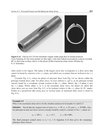
Figure 6.12 Failure of a 15 mm diameter copper water pipe due to excess pressure
from freezing. In the cross section on the right, note that failure occurred on a plane inclined
◦
45 to the tube surface, which is the plane of the maximum shear stress. (Photos by
R. A. Simonds.)
other circles is the largest. The radius of the largest circle now corresponds to a shear stress that
cannot be found by rotations in the x-y plane, and which acts on planes that are inclined to the x-y
plane.
Consider Fig. 6.11, where the planes of principal shear from Fig. 6.8 are shown within the
principal normal stress cube. For plane stress, we have defined σ 1 and σ 2 as the principal normal
stresses found by a coordinate system rotation in the x-y plane. Hence, the 1-2 plane is also
the x-y plane. Where either τ 1 or τ 2 is the maximum shear stress, the planes on which this
◦
shear stress acts are seen from Fig. 6.11 to be inclined relative to the x-y plane by 45 angles.
Failure of a pressurized tube along such an inclined plane of maximum shear stress is shown in
Fig. 6.12.
Example 6.4
What is the maximum shear stress for the situation analyzed in Examples 6.1 and 6.2?
Solution Recall that the original state of stress is σ x = 95, σ y = 25, and τ xy = 20 MPa. Also,
the principal normal and shear stresses already found by analysis confined to the x-y plane are
σ 1 = 100.3, σ 2 = 19.7, τ 3 = 40.3MPa
The third principal normal stress is σ 3 = σ z = 0. Equation 6.18 then gives the remaining
principal shear stresses: