Page 345 - Mechanical Behavior of Materials
P. 345

346                                             Chapter 8  Fracture of Cracked Members


               As listed in the References, Barsom (1987) is a collection of papers reporting some of the early
            work on fracture mechanics by Griffith, Irwin, and others.


            8.3.2 Stress Intensity Factor, K

            The stress intensity factor concept, which has already been introduced, needs to be defined in a more
            complete manner. In general terms, K characterizes the magnitude (intensity) of the stresses in the
            vicinity of an ideally sharp crack tip in a linear-elastic and isotropic material.
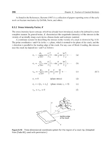
               A coordinate system for describing the stresses in the vicinity of a crack is shown in Fig. 8.10.
            The polar coordinates r and θ lie in the x-y plane, which is normal to the plane of the crack, and the
            z-direction is parallel to the leading edge of the crack. For any case of Mode I loading, the stresses
            near the crack tip depend on r and θ as follows:


                                     K I    θ  	     θ    3θ
                              σ x = √    cos   1 − sin  sin   + ···   (a)
                                     2πr    2        2    2

                                     K I    θ  	     θ    3θ
                              σ y = √    cos   1 + sin  sin   + ···   (b)
                                     2πr    2        2    2

                                     K I     θ   θ    3θ
                              τ xy = √    cos  sin  cos  + ···        (c)              (8.7)
                                      2πr    2   2     2
                              σ z = 0          (plane stress)         (d)


                              σ z = ν σ x + σ y  (plane strain; ε z = 0)  (e)
                              τ yz = τ zx = 0                         (f)


                                                           σ y
                                                              τ xy
                                                y              τ  yz
                                                    σ           τ  zx
                                                     x
                                                                σ z  x
                                                   r  θ

                                                       leading edge
                                                       of the crack


                                                        z

            Figure 8.10 Three-dimensional coordinate system for the region of a crack tip. (Adapted
            from [Tada 85]; used with permission.)
   340   341   342   343   344   345   346   347   348   349   350