
Page 351 - Mechanical Behavior of Materials
P. 351
352 Chapter 8 Fracture of Cracked Members
P
M
T b
h K = FS πa
g
α = a/b
β = 1 – α
a
P
(a) Axial load P: S g = , F = 1.12 (10%, a/b ≤ 0.21)
πb 2
1 1 3 2 3 4
F = 1 + β + β − 0.363β + 0.731β
2β 1.5 2 8
4M
(b) Bending moment M: S g = , F = 1.12 (10%, a/b ≤ 0.12)
πb 3
3 1 3 2 5 3 35 4 5
F = 1 + β + β + β + β + 0.537β
8β 2.5 2 8 16 128
2T
(c) Torsion T, K = K III : S g = , F = 1.00 (10%, a/b ≤ 0.09)
πb 3
3 1 3 2 5 3 35 4 5
F = 1 + β + β + β + β + 0.208β
8β 2.5 2 8 16 128
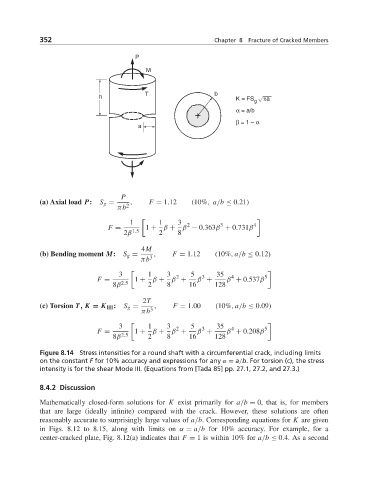
Figure 8.14 Stress intensities for a round shaft with a circumferential crack, including limits
on the constant F for 10% accuracy and expressions for any α = a/b. For torsion (c), the stress
intensity is for the shear Mode III. (Equations from [Tada 85] pp. 27.1, 27.2, and 27.3.)
8.4.2 Discussion
Mathematically closed-form solutions for K exist primarily for a/b = 0, that is, for members
that are large (ideally infinite) compared with the crack. However, these solutions are often
reasonably accurate to surprisingly large values of a/b. Corresponding equations for K are given
in Figs. 8.12 to 8.15, along with limits on α = a/b for 10% accuracy. For example, for a
center-cracked plate, Fig. 8.12(a) indicates that F = 1 is within 10% for a/b ≤ 0.4. As a second