Page 352 - Mechanical Behavior of Materials
P. 352

Section 8.4  Application of K to Design and Analysis                       353


                                               b
                                                    h
                                                P
                                                      t
                                                a

                                 P           a            1            a
                         K =F P √ ,      α =  ,    F P = √       (10%,   ≤ 0.3)
                                t b          b            πα           b
                                            πα
                             1.297 − 0.297 cos
                                             2          a
                         F P =     √               (0 ≤   ≤ 1)
                                     sin πα             b
            Figure 8.15 Stress intensity factor for forces applied to the faces of a central crack in a plate
            with h/b ≥ 2. A simple expression is given for F P that is within 10% for a limited range of
            α = a/b, as is an expression valid for any α. (Equations from [Tada 85] pp. 2.22 and 2.23.)

                          30

                                                                   P
                          25       P                     K = F P t   b
                                    a
                                         h
                          20
                                           t
                        F
                         P
                          15          b
                                       h/b = 0.6
                          10

                           5

                           0
                            0.2     0.3     0.4     0.5      0.6     0.7     0.8
                                                   α = a/b


                          2 + α                      2        3      4
                  F P =         (0.886 + 4.64α − 13.32α + 14.72α − 5.6α )  (a/b ≥ 0.2)
                        (1 − α) 3/2
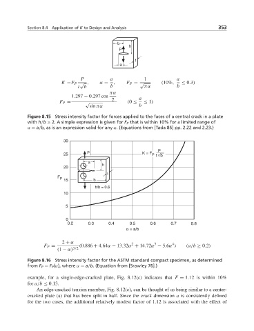
            Figure 8.16 Stress intensity factor for the ASTM standard compact specimen, as determined
            from F P = F P (α), where α = a/b. (Equation from [Srawley 76].)

            example, for a single-edge-cracked plate, Fig. 8.12(c) indicates that F = 1.12 is within 10%
            for a/b ≤ 0.13.
               An edge-cracked tension member, Fig. 8.12(c), can be thought of as being similar to a center-
            cracked plate (a) that has been split in half. Since the crack dimension a is consistently defined
            for the two cases, the additional relatively modest factor of 1.12 is associated with the effect of
   347   348   349   350   351   352   353   354   355   356   357