
Page 360 - Mechanical Behavior of Materials
P. 360
Section 8.5 Additional Topics on Application of K 361
S P
M
b t
a
t a
2t
b
2b
(a) (b)
P P
M
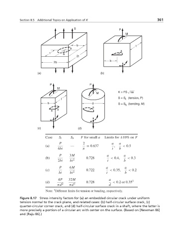
M K = FS πa
t S = S (tension, P)
t
b d S = S (bending, M)
b
a
a a
(c) (d)
Case S t S b F for small a Limits for ±10% on F
P 2 a a
(a) — = 0.637 , < 0.5
4bt π t b
P 3M a a
(b) 0.728 < 0.4, < 0.3
2bt bt 2 t b
P 6M a a
(c) 0.722 < 0.35, < 0.2
bt bt 2 t b
4P 32M a 1
(d) 0.728 < 0.2or0.35
πd 2 πd 3 d
1
Note: Different limits for tension or bending, respectively.
Figure 8.17 Stress intensity factors for (a) an embedded circular crack under uniform
tension normal to the crack plane, and related cases: (b) half-circular surface crack, (c)
quarter-circular corner crack, and (d) half-circular surface crack in a shaft, where the latter is
more precisely a portion of a circular arc with center on the surface. (Based on [Newman 86]
and [Raju 86].)