
Page 364 - Mechanical Behavior of Materials
P. 364
Section 8.5 Additional Topics on Application of K 365
S 4
a K = 1.12 k S π
A t
h 3 k = 3
t
F = 1
K K = FS πa
t S c B
c 2
b
= '
1 K = F S π
d
K = F S π , d = a = c +
d
3
F = 0.5(3 – d)[1 + 1.243(1 – d) ] 0
d
0 0.1 0.2 0.3 0.4 0.5
/c
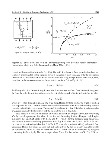
Figure 8.20 Stress intensities for a pair of cracks growing from a circular hole in a remotely
loaded wide plate, a
b, h. (Equation from [Tada 85] p. 19.1.)
is used to illustrate this situation in Fig. 8.20. The solid line shown is from numerical analysis and
is closely approximated by the equation given. If the crack is short compared with the hole radius,
the solution is the same as for a surface crack in an infinite body, except that the stress is k t S, being
amplified by the stress concentration factor, in this case k t = 3 from Fig. A.11(a):
√
K A = 1.12 k t S πl (8.24)
In this equation, l is the crack length measured from the hole surface. Once the crack has grown
far from the hole, the solution is the same as for a single long crack of tip-to-tip length 2a,for which
√
K B = FS πa (8.25)
where F = 1 for this particular case of a wide plate. Hence, for long cracks, the width of the hole
acts as part of the crack, and the fact that the material removed to make the hole is missing from the
crack faces is of little consequence. The exact K first follows K A , then falls below it and approaches
K B , agreeing exactly for large l beyond the range of the plot of Fig. 8.20.
Most cases of a crack at an internal or surface notch can be roughly approximated by using
K A for crack lengths up to that where K A = K B , and then using K B for all longer crack lengths.
Equations 8.24 and 8.25 apply, with the k t and F = F(a/b) for the particular case being used,
and with the nomenclature being generalized as in Fig. 8.21. Note that k t and S in Eq. 8.24 must
be consistently defined and also that F in Eq. 8.25 is usually consistent with S g calculated from
gross area. Hence, the values k tn used with net section stress S n that are usually available need to
be converted to values k tg that are consistent with S g , which can be accomplished by using the
relationship k tn S n = k tg S g . The crack length where K A = K B , labeled as l = l in Fig. 8.20, can